C-3.5 Describe Drawing Projections
You need accurate information to complete a piping installation, no matter how simple or complex the system.
Information for a project is provided by mere drawings or by drawings and specifications. Drawings provide dimensions and details of materials of construction. Specifications give details on installation procedures and the standards required for materials. Some installations may have the specifications and all other pertinent information on the drawings in the form of notes.
These drawings are known as working drawings. Working drawings are sometimes referred to as blueprints, a term that is a carry-over from when all prints had a blue background and the lines and lettering were in white.
Types of Views Used in Drawings
The two main types of views (or projections) used in drawings are:
- pictorial
- orthographic
Pictorial Views
Pictorial views show how something should physically look when completed. There are three types of pictorial views:
- perspective
- isometric
- oblique
Perspective View
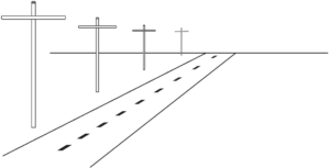
A perspective view presents a building or an object just as it would look to you. A perspective view has a vanishing point: that is, lines that come together in the distance as they move away from you. For example, in Figure 1, we see a road and line of telephone poles. Even though the poles get smaller in their actual measurement, we recognize them as being the same size, but more distant.
Isometric View
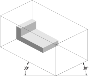
An isometric view is a three-dimensional view. The plumb lines are vertical. The horizontal lines are set at 30° angles from a line parallel to the bottom of the page. Isometric views have no vanishing point, so the objects do not appear as they would in a perspective view. Lengths are exact on isometric drawings only when the item is parallel to one of the axes of the drawing. Figure 2 shows an isometric view of a simple object, as well as the lines that represent the three dimensions.
Oblique View
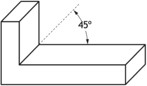
An oblique view is similar to an isometric view, except that the face or front view is drawn to exact scale and the oblique lines are extended at a 30° to 45° angle to create a three-dimensional representation (Figure 3).
Orthographic Views
Orthographic views (or orthographic projections) are the most common views used for working drawings. Each projection is a view that shows only one face of an object, such as the front, side, top or back. These views are not pictorial. Orthographic views are used in all fields of architecture and engineering. Figure 4 shows how the pictorial view from Figure 2 is opened to produce six orthographic views. Figure 5 shows how the same views are drawn.
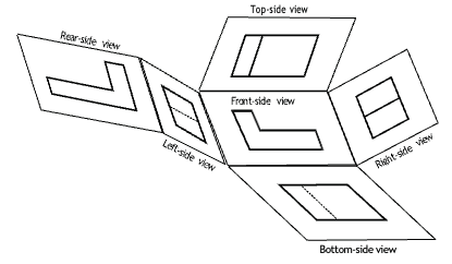
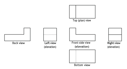
Unless the object is very complex, only the front, top and right-side views are necessary. If the object has a uniform thickness, only two views are necessary. The front, left, back and right views are also referred to as elevations.
Piping systems normally require two or three orthographic views, either a plan view and one elevation drawing or a plan view and two elevation drawings. Some systems may be illustrated with a three-dimensional (isometric) drawing or with three orthographic drawings.
The plan (top), the front and the side views are the three usual orthographic views from which you should choose the views to represent piping systems. If the side view shown is not specified, the right side is normally used. Bottom and back views are used less often.
Floor Plan
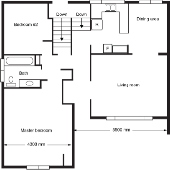
The floor plan is an orthographic view of a building that is commonly the most important projection for the pipe trade worker because it gives the most pertinent information about the building. Floor plans identify room names and numbers, place them within the building as a whole, and provide the following relevant info:
- room dimensions
- size, location, and swing of doors
- size and location of windows
- size and spacing of beams and floor joists
Floor plans show the location of:
- plumbing fixtures
- tub drains
- appliances
- cabinets, closets and shelves
Elevation View
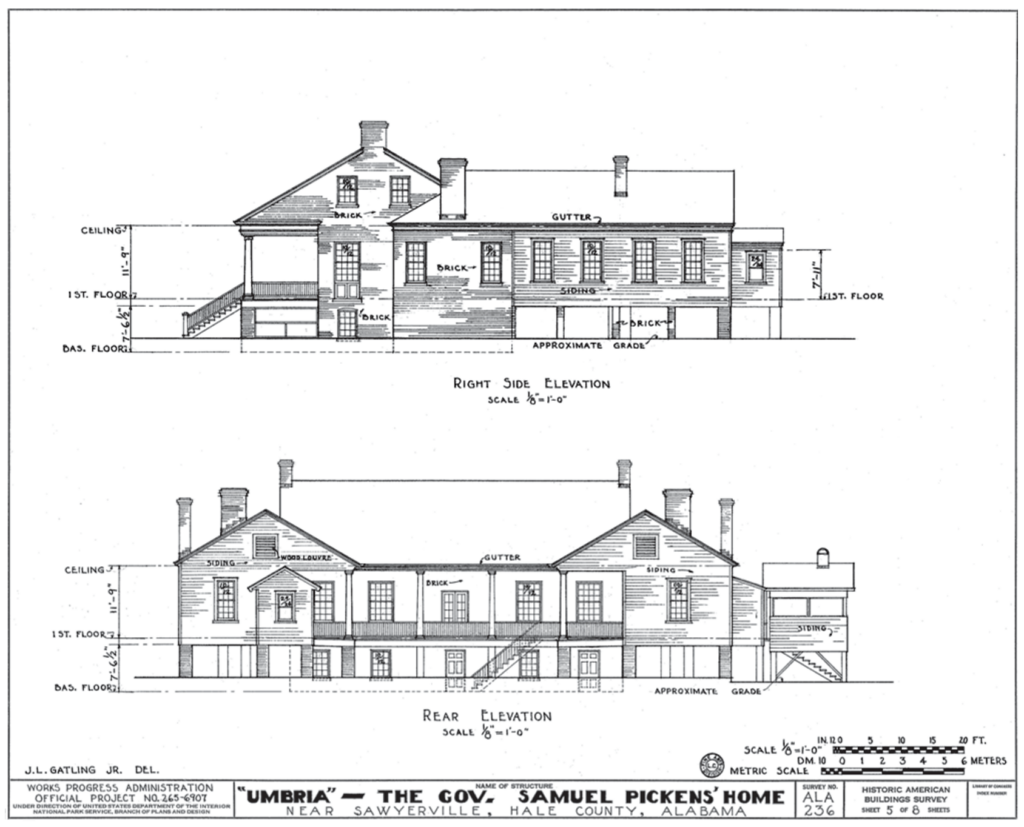
An elevation view is a front, side, or back orthographic projection of a building, that contains important information such as:
- finished grade or ground level
- exterior details, including material, dimensions roof pitch -see figure 7
- scale
Section Plan
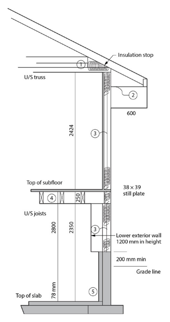
A section drawing provides details on a cross-section of a building or wall. The section drawing is usually quite detailed, showing scale, material selection, dimensions and typical construction choices.

Self-Test C-3.5: Describe Drawing Projections
Complete Self-Test C-3.5 and check your answers.
If you are using a printed copy, please find Self-Test C-3.5 and Answer Key at the end of this section. If you prefer, you can scan the QR code with your digital device to go directly to the interactive Self-Test.
References
BCcampus. (n.d.). Playlist: Tools and equipment videos. BCcampus MediaSpace. https://media.bccampus.ca/playlist/details/0_3g8xp22x/categoryId/175673 Playlist Details – Trades Access Common Core Line C: Tools and Equipment Videos – BCcampus
BC Industry Training Authority. (2019). Piping trades apprenticeship program: Use Tools and Equipment—Level 1 harmonized [Binder]. Crown Publications, Queen’s Printer for British Columbia. https://www.crownpub.bc.ca/Product/Details/7960000261_S
- Plumber: Competency C-2 Interpret Drawings and Specifications
- Steamfitter: Competency C-2 Interpret Drawings and Specifications
- Sprinkler Fitter: Competency C-2 Interpret Drawings and Specifications
Camosun College. (2019). Line D: Tools and Equipment—Competency D-3: Competency D-3: Read Drawings and Specifications (Rev. ed.) [Learning guide]. BCcampus. https://collection.bccampus.ca/textbook/yxJ3AwTa/
Camosun College. (2015). Trades Access Common Core Competency D-3: Competency D-3: Read Drawings and Specifications. Victoria, B.C.: Crown Publications. Download for free from the B.C. Open Textbook Collection (https://open.bccampus.ca/browse-ourcollection/find-open-textbooks/).
Media Attributions
All figures are sourced from Industry Training Authority (2019) and/or Camosun College (2019) and are used under the Creative Commons Attribution 4.0 (CC BY 4.0) licence unless otherwise noted. Images copyrighted by the BC Industry Training Authority are licensed under a Creative Commons Attribution-NonCommercial-ShareAlike 4.0 (CC BY-NC-SA 4.0) licence.