Answer Key: Self-Test C-3.3
- Why are piping symbols used?
- to visually represent pipes, fittings, etc.
- State the two basic requirements for symbols.
- must be simple
- must be easy to draw
- Why are single-line symbols usually used in piping drawings?
- because they are simplest and easiest to draw
- Lengths of valves and fittings in single-line drawings are always drawn to scale.
- false
- Flanged or welded valves and fittings in double line drawings are always drawn to scale.
- true
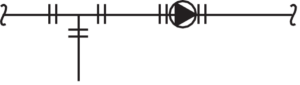
- The joint in Figure 1 is
- flanged
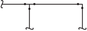
- The joint in Figure 2 is
- butt welded
- The joint in Figure 3 is
- butt welded

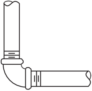
- The joint in Figure 4 is
- screwed
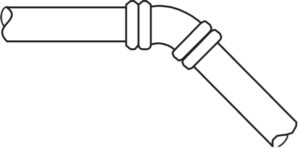
- The joint in Figure 5 is
- flanged
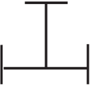
- The symbol in Figure 6 is a
- tee
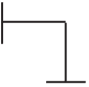
- The symbol in Figure 7 is a
- 90° elbow
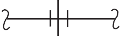
- The symbol in Figure 8 is a
- union
- The symbol in Figure 9 is a
- gate valve

- The symbol in Figure 10 is a
- globe valve

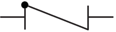
- The symbol in Figure 11 is a
- check valve
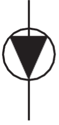
- The symbol in Figure 12 is a
- pump
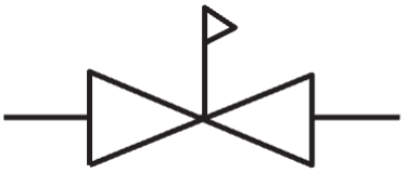
- The symbol in Figure 13 is a
- pressure-reducing valve
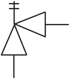
- The symbol in Figure 14 is a
- safety valve
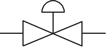
- The symbol in Figure 15 is a
- control valve
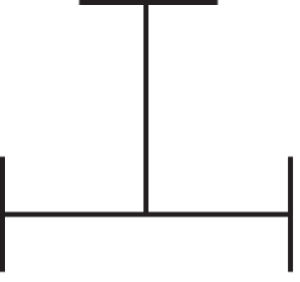
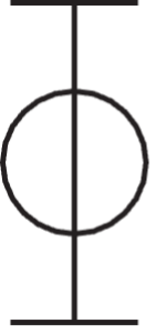
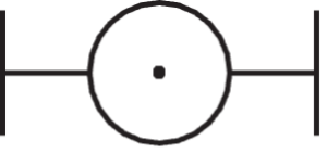
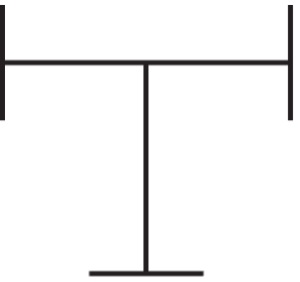
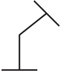
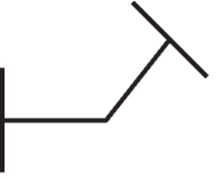
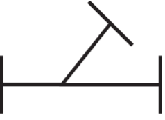
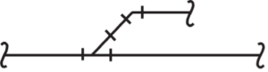
- Draw the right view of the following front views.
|
|
Front view |
Right view |
|
a. |
 |
|
|
b. |
 |
|
|
c. |
 |
|
|
d. |
 |
|
|
e. |
 |
|
|
f. |
 |
|
|
g. |
 |
|
|
h. |
 |
|
|
i. |
 |
|


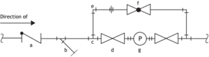
- Identify the symbols A to G in Figure 16.
-
- check valve
- strainer
- tee
- gate valve
- 90° elbow
- globe valve
- pump