C-3.4 Describe Lettering and Dimensioning of Piping Diagrams
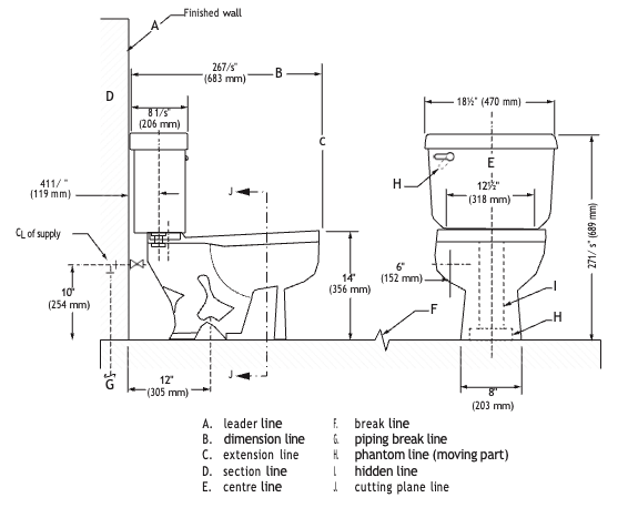
Standard lines for drawings have been developed so that lines in every drawing or sketch convey the same meaning or information. In order to convey that meaning, the lines used in technical drawings have both a definite pattern and a definite thickness. Some lines are complete and others are broken. Some lines are thick and others are thin. A visible line, for example, is used to show the edges (or outline) of an object and to make it stand out for easy reading. This line is made thick and dark. A centre line, on the other hand, which locates the precise centre of a hole or shaft, is drawn thin and made with long and short dashes. This makes it easily distinguishable from the visible lines.
Study the standard line thicknesses (or line weights) shown in Figure 1 and practise making them. Use a fairly sharp pencil when you draw. Maintaining an even, consistent pressure will make it easier for you to produce acceptable lines.
In computer drafting, the line shape remains the same, but line thickness may not vary as in manually created drawings. Some lines, such as centre lines, may not cross in the same manner as in a manual drawing. For most computer drafting, line thickness is not important.
|
Type |
Weight |
Line |
Description |
|
Object line Margin line |
Heavy |
 |
Solid line to show visible shape, edges and outlines. |
|
Hidden body line |
Medium |
 |
Broken line of short dashes to show hidden object lines not visible to the eye. |
|
Phantom line |
Light |
 |
Broken line of short dashes to show alternate positions or movement of a part. |
|
Section line |
Light |
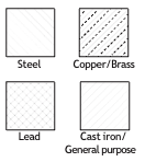 |
Unbroken lines arranged in a pattern, usually straight and at a 45º diagonal. |
|
Projection line |
Light |
 |
Unbroken lines that extend away from the object or feature for emphasis. |
|
Centre line |
Light |
 |
A broken line of long and short dashes to show the centre of an object. |
|
Extension line/ Dimension line |
Light |
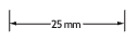 |
Extension lines are small lines that extend outward from an object or feature. Dimension lines span between the extension lines with arrow heads and a given dimension. |
|
Leader line |
Light |
 |
Unbroken line usually drawn at an angle often with a “dogleg” and an arrowhead. A dot is used in place of an arrowhead where a surface is referenced. Usually accompanied by a label. |
|
Cutting plane line |
Heavy |
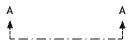 |
A broken line of one long and two short dashes to show an imaginary cross-section. The arrowheads show the direction from where the cross-section is viewed. A corresponding image will show the view of A. |
|
Break lines for wood and metal |
Heavy |
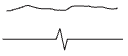 |
Unbroken freehand or straight zig-zag lines to abbreviate longer spans of wood or metal. |
|
Break lines for piping |
Heavy |
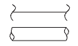 |
Curled lines to abbreviate a longer span of pipe. |
When you are able to consistently reproduce lines of equal blackness and thickness, study Figure 1, which shows the nature of each line and explains how they are used in a technical drawing. You must be able to identify each line by name and describe its application.
Standard Lettering
The letters and numbers on a drawing or sketch are as important as the lines. Scribbled, smudged or badly written letters and numbers can become impossible to read. This may lead to time- consuming and costly errors. Lettering is necessary to describe:
- the name or title of a drawing
- when it was made
- the scale
- who sketched it
- the dimensions
- the special notations that describe the size
- the materials to be used
- the construction methods
In making drawings and sketches, there is a need for simplicity, uniformity and speed of execution.
The American standard vertical letters have become the most accepted style of lettering used in the production of manual drafting (Figure 2). Font styles and sizes may vary in computer drafting. Note that all letters are written as capital (or uppercase) letters. Practise these characters, concentrating on forming the correct shape. Remember that letters and numbers must be black so that they will stand out and be easy to read.
Lettering and figures should have the same weight and darkness as hidden lines.
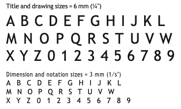
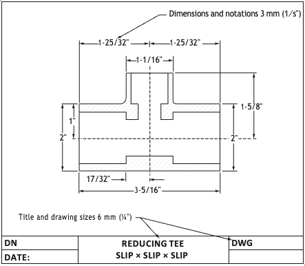
Figure 3 shows a simple drawing. Notice that the dimensions are given between arrows that point to extension lines. By using this method, the dimensions do not get in the way of the drawing. One extension line can be used for several dimensions. Notice also that the titles require larger letter sizes than those used for dimensions and notations. It is important that the title and sketch number on your sketches stand out, as shown in Figure 3. When you begin lettering, you may wish to use very light lettering guide lines to ensure uniformity in lettering size and alignment.
Typically, drawings are placed on the page within containment lines called a border. The border lines help bring the drawing together and give it a professional feel.
On an [latex]8 \frac{1}{2}\text{"} \times 11\text{"}[/latex] sheet of paper, borders are drawn approximately 1 cm from the edge for the top and sides, but approximately 2 cm from the bottom to compensate for an optical illusion that occurs when the border is equal around all four sides. Unless the bottom border is larger, the eye is drawn to the bottom of the page because the border appears too short.

Self-Test C-3.4: Describe Lettering and Dimensioning of Piping Diagrams
Complete Self-Test C-3.4 and check your answers.
If you are using a printed copy, please find Self-Test C-3.4 and Answer Key at the end of this section. If you prefer, you can scan the QR code with your digital device to go directly to the interactive Self-Test.
References
BCcampus. (n.d.). Playlist: Tools and equipment videos. BCcampus MediaSpace. https://media.bccampus.ca/playlist/details/0_3g8xp22x/categoryId/175673 Playlist Details – Trades Access Common Core Line C: Tools and Equipment Videos – BCcampus
BC Industry Training Authority. (2019). Piping trades apprenticeship program: Use Tools and Equipment—Level 1 harmonized [Binder]. Crown Publications, Queen’s Printer for British Columbia. https://www.crownpub.bc.ca/Product/Details/7960000261_S
- Plumber: Competency C-2 Interpret Drawings and Specifications
- Steamfitter: Competency C-2 Interpret Drawings and Specifications
- Sprinkler Fitter: Competency C-2 Interpret Drawings and Specifications
Camosun College. (2019). Line D: Tools and Equipment—Competency D-3: Competency D-3: Read Drawings and Specifications (Rev. ed.) [Learning guide]. BCcampus. https://collection.bccampus.ca/textbook/yxJ3AwTa/
Camosun College. (2015). Trades Access Common Core Competency D-3: Competency D-3: Read Drawings and Specifications. Victoria, B.C.: Crown Publications. Download for free from the B.C. Open Textbook Collection (https://open.bccampus.ca/browse-ourcollection/find-open-textbooks/).
Media Attributions
All figures are sourced from Industry Training Authority (2019) and/or Camosun College (2019) and are used under the Creative Commons Attribution 4.0 (CC BY 4.0) licence unless otherwise noted. Images copyrighted by the BC Industry Training Authority are licensed under a Creative Commons Attribution-NonCommercial-ShareAlike 4.0 (CC BY-NC-SA 4.0) licence.