C-2.3 Wiring Diagrams and Symbols
Wiring Diagrams
A wiring diagram is a roadmap of an electrical circuit. Using it, a service technician can analyze the circuit. Diagrams are also used to systematically troubleshoot problems in a circuit. There are four main types of wiring diagrams:
- Pictorial
- Block and line
- Wiring
- Schematic
Pictorial Diagrams
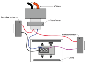
A pictorial diagram shows the circuit components in detail as they really look and indicates how the wiring is attached (Figure 1). These diagrams can be used to locate components in a complex system. A pictorial diagram is best suited for individuals with little knowledge of wiring, as the diagram can be followed easily because the components can be recognized.
Block and Line Diagrams
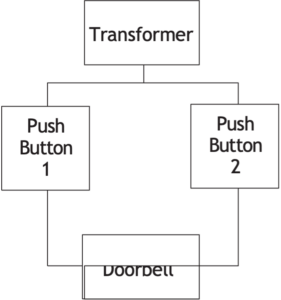
The block diagram, also called a functional block diagram or block and line diagram (Figure 2), is used to describe the sequence of circuit operation. This diagram indicates, by functional descriptions, which components must operate first in order to get a final outcome. It does not make reference to specifics, like device symbols or related wire connections. These types of diagrams are used widely for troubleshooting as they relate directly to a sequence of operation.
Wiring Diagrams
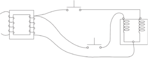
A wiring diagram shows the relative layout of the circuit components using the appropriate symbols and the wire connections (Figure 3). Although a wiring diagram is easy to use for wiring an installation, it is sometimes difficult to understand circuit operation because the components are shown as symbols. It is not as applicable for troubleshooting.
Schematic Diagrams
A schematic diagram, often called a ladder diagram, is intended to be the simplest, most orderly form of an electrical circuit. This diagram shows the circuit components as symbols on horizontal lines that resemble the rungs of a ladder, without regard to their physical location (Figure 4).
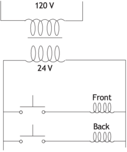
The power source lines of the circuit are parallel and form the rails or sides of the ladder. The loads and switches are drawn between the power source lines, forming the rungs of the ladder.
Ladder diagrams make it easier to tell which loads are wired in series and which are in parallel. As well, no two lines in a ladder diagram ever cross, so it is less likely to get wiring paths mixed up. However, using a ladder diagram requires more knowledge of electricity and electrical symbols and components than a pictorial diagram or schematic. This is because they do not look like the real components. A service technician must be able to look at the diagram and relate it to the actual unit. They must know the unit components and their corresponding electrical symbols. On most diagrams, these symbols are keyed to a table that names the components.
Symbols
Electrical symbols are used as a shorthand method to represent the various electrical components of a circuit. The following are international schematic symbols for the most commonly used electrical devices.
|
Symbol |
Name |
Description |
 |
Single pole, single throw switch (SPST) |
Opens and closes one circuit |
 |
Single pole, double throw switch (SPDT) |
Opens and closes alternate circuits |
 |
Double pole, single throw switch (DPST) |
Opens and closes two separate circuits simultaneously |
 |
Double pole, double throw switch (DPDT) |
Opens and closes two alternate circuits simultaneously |
 |
Flow switch |
Closes on flow (normally open [NO]) |
 |
Flow switch |
Opens on flow (normally closed [NC]) |
 |
Temperature switch |
Opens a circuit when temperature rises |
 |
Temperature switch |
Closes a circuit when temperature rises |
 |
Pressure switch |
Closes a circuit when pressure rises |
 |
Pressure switch |
Opens a circuit when pressure rises |
 |
Float switch |
Closes a circuit when liquid level rises |
 |
Float switch |
Opens a circuit when liquid level rises |
 |
Load |
Typically represents a wire winding or coil (e.g., gas valve, light, motor) |
 |
Relay |
Typically represents a coil in a relay |
 |
Wire winding/coil |
Similar to “load” above |
 |
Transformer |
Transformers increase or decrease voltage between primary and secondary circuits |
 |
Normally open (NO) relay contact |
Disallows current flow unless relay coil is energized |
 |
Normally closed (NC) relay contact |
Allows current flow while coil is not energized |
 |
Voltage source for direct current |
Indicates a battery or other source of DC |
 |
Resistor |
Indicates a constant resistance in a circuit |
 |
Variable resistor |
Indicates a resistance that can be changed in a circuit |
 |
Pump |
The point of the shaded triangle indicates the direction of flow |
 |
Fuse |
Opens a circuit when too much current flows |
 |
Fuse |
Opens a circuit when too much current flows |
 |
Ground (Earth) |
A connection to the earth that has no voltage potential |
 |
Wire connection |
The dot indicates a connection between wires |

Self-Test C-2.3: Wiring Diagrams and Symbols
Complete Self-Test C-2.3 and check your answers.
If you are using a printed copy, please find Self-Test C-2.3 and Answer Key at the end of this section. If you prefer, you can scan the QR code with your digital device to go directly to the interactive Self-Test.
References
BCcampus. (n.d.). Playlist: Tools and equipment videos. BCcampus MediaSpace. https://media.bccampus.ca/playlist/details/0_3g8xp22x/categoryId/175673 Playlist Details – Trades Access Common Core Line C: Tools and Equipment Videos – BCcampus
BC Industry Training Authority. (2019). Piping trades apprenticeship program: Use Tools and Equipment—Level 1 harmonized [Binder]. Crown Publications, Queen’s Printer for British Columbia. https://www.crownpub.bc.ca/Product/Details/7960000261_S
- Plumber: Competency O-1 Use the Principles of Electricity
- Steamfitter: Level 2 Competency K-1 Use the Principles of Electricity
- Sprinkler Fitter: Competency C-1 Use Mathematics and Science
Camosun College. (2019). Line D: Tools and Equipment—Competency D-2: Apply Science Concepts to Trades Applications (Rev. ed.) [Learning guide]. BCcampus. https://collection.bccampus.ca/textbook/fkXxtNTn/
Camosun College. (2015). Line E – Electrical fundamentals competency E-1: Describe the Basic Principles of Electricity. BCcampus.
https://collection.bccampus.ca/textbook/Nf7jVbAg/
Camosun College. (2015). Line E – Electrical fundamentals competency E-2: Identify common circuit components and their symbols. BCcampus.
https://collection.bccampus.ca/textbook/fGcTBtJh/
Camosun College. (2015). Line E – Electrical fundamentals competency E-3: Explain Wiring Connections. BCcampus.
https://collection.bccampus.ca/textbook/qV9cMUkU/
Media Attributions
All figures are sourced from Industry Training Authority (2019) and/or Camosun College (2019) and are used under the Creative Commons Attribution 4.0 (CC BY 4.0) licence unless otherwise noted. Images copyrighted by the BC Industry Training Authority are licensed under a Creative Commons Attribution-NonCommercial-ShareAlike 4.0 (CC BY-NC-SA 4.0) licence.
A drawing that shows how wires and components are connected in a circuit. (Section C-2.3)
A diagram that shows electrical parts as they actually look in real life. (Section C-2.3)
A diagram that shows how parts of a system work together in steps. (Section C-2.3)
A diagram that uses symbols to show how an electrical circuit works. (Section C-2.3)
A type of schematic diagram that looks like a ladder and shows how a circuit works. (Section C-2.3)
Simple drawings used to represent electrical parts in a diagram. (Section C-2.3)
A diagram that shows electrical parts as they actually look in real life. (Section C-2.3)