C-3.6 Use Drawing Projections
Orthographic Fitting Symbols
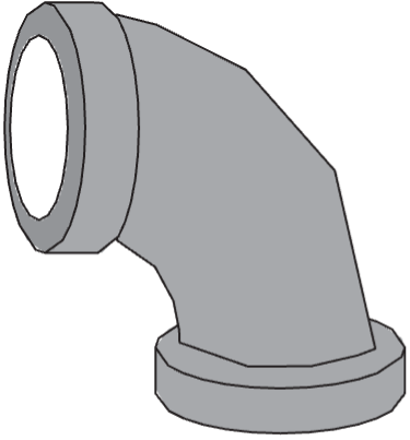
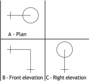
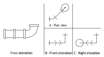
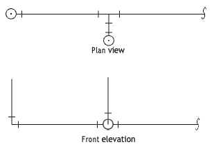
To help you recognize piping symbols in different orthographic views, the following fittings are shown first in a pictorial drawing (Figure 1) then as three orthographic views (Figure 2).
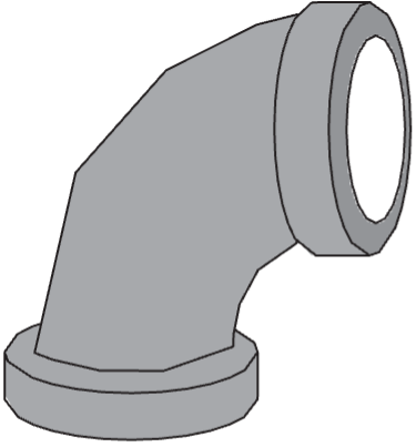
In Figure 3, the same elbow is shown from the opposite side. Figure 4 reflects the corresponding changes to the orthographic views.
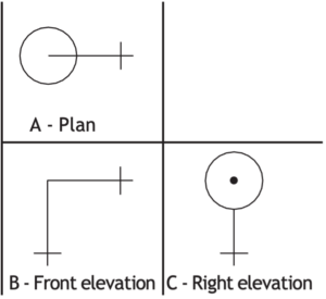
As stated previously, side and front views are normally called elevations and at times are referred to as sections, especially if the drawing only contains part of a piping system.
Figure 5 shows a drawing of a tee and the three standard orthographic views. Notice that the right view, facing the end of the tee, cannot be distinguished from the same view facing the end of a 90° elbow. This is why multiple views of an object are preferred for clarity.
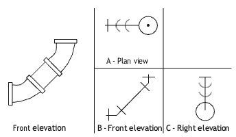
The frontal drawing of a 45° elbow in Figure 6 is shown with the corresponding standard orthographic views. Notice the curved fitting lines dictate that part of the fitting is not at right angles in the view.
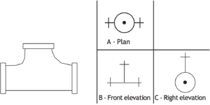
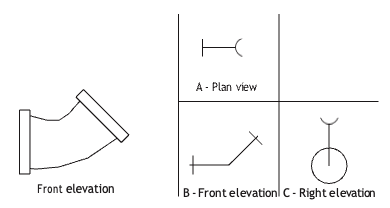
Each fitting has a different appearance depending on the direction from which it is viewed. With practice, you will be able to quickly draw three orthographic views for any fitting. If you know what the fitting is and see one view of it, with practice, you will be able to draw the remaining views.
Example
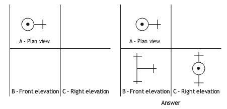
Cover the answer on the right and draw in the remaining views of the tee for which the plan view is given in Figure 7.
Use Orthographic Piping Drawings
As we have discussed, when orthographic projections are used, three views of an object are usually shown. These are typically the plan view, the front view and a side view.
The two or three orthographic views used for piping drawings are usually shown grouped together in typical fashion. All views are required for a complete understanding of the piping system. It is not unusual to find only one orthographic view of a two- or three-dimensional piping run. A single view would only be used when the second view would convey little or no information. For example, the plan view of a horizontal drainage piping system is often shown without any accompanying elevation drawings, as there may be no elevation changes (other than the pipe’s slope).
The chief advantage of orthographic drawings is that they can be used to pinpoint the exact location of components. For example, orthographic piping layouts drawn on building plans show the exact relationship between the piping system and the building’s features. Any lengths that are on the drawing are considered to be accurate. Because orthographic drawings are so often used to show exact component locations, they are usually drawn to scale.
Orthographic drawings have limitations. They are not suitable for complicated systems that have many overlapping pipes, valves and fittings. An orthographic drawing of an intricate piping system can confuse even the most experienced blueprint reader. Orthographic drawings of complicated piping systems are generally accompanied by an isometric diagram that shows the system in one clear view.
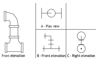
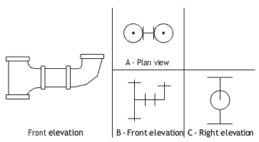
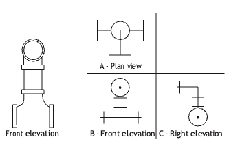
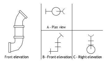
Figures 8 to 15 show various orthographic views of simple piping systems. Be sure to allow for hidden items when considering different views. In each case, two of the three views are enough to depict clearly the piping layout. For example, if the front views were not chosen in Figures 8 and 9, the figures could appear to depict two tees and two elbows, respectively.
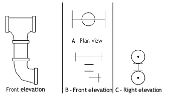
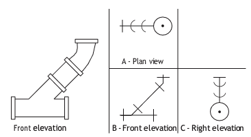
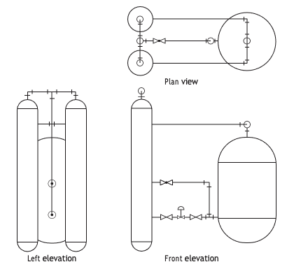
Note that in Figure 18, the plan view is unable to show the control valve and isolation valves. A supplementary elevation view is therefore required to understand the piping arrangement.
Once you can distinguish which view of a piping system is depicted, you will be able to read and understand the drawing.
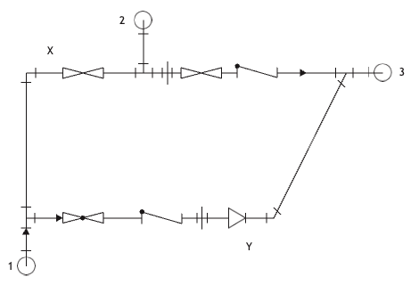
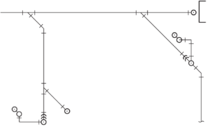
Figure 19 shows an orthographic plan view of a portion of a piping system, incorporating standard graphic piping symbols. The small solid arrowheads placed on the pipeline indicate the direction of flow. The flow originates from below point 1. The direction of flow is through section X to point 2 and on to point 3. Point 3 is also supplied by flow through piping section Y when the bypass globe valve is open. Note also the direction of flow indicated by the check valve symbols.

Self-Test C-3.6.1: Use Drawing Projections
Complete Self-Test C-3.6.1 and check your answers.
If you are using a printed copy, please find Self-Test C-3.6.1 and Answer Key at the end of this section. If you prefer, you can scan the QR code with your digital device to go directly to the interactive Self-Test.

Use Isometric Piping Drawings
Isometric drawings are used because they clearly represent both simple and complicated piping arrangements. This clarity comes from using angular lines to represent the three dimensions, much like a picture. The three dimensions of length, width and height are drawn along the isometric axes shown in Figure 20. The lengths of objects running parallel to these axes can be drawn to scale.
Lines at other angles will not be to scale.
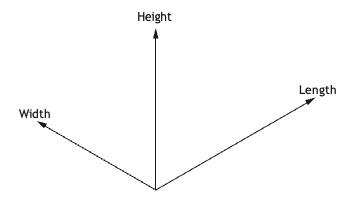
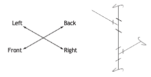
The two vertical directions (up and down) are represented by vertical lines. The four horizontal directions (front and back; left and right) are represented by lines at 30° from the horizontal. These six directions are parallel to the three isometric axes, as shown in Figures 21 and 22.
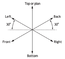
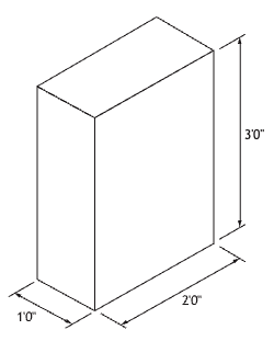
Most piping is installed parallel to these directions, so the piping can be drawn along the isometric lines. Lines that are not isometric on scaled drawings will not be to scale. Notice the clarity of the piping layout shown in Figure 23.
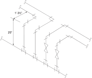
This type of drawing of a piping layout can be easily drawn with practice. The drawing style is useful for taking off materials such as the type and number of fittings and the lengths of pipe required. This can only be done accurately if the drawing is to scale or dimensions are provided.
Isometric lines are parallel to the three isometric axes. They are also drawn parallel to one of the three edges of the isometric plane. Figure 24 shows the isometric lines that correspond to the isometric axes. Notice that the pipes, fittings and lines indicating fittings, joints or connections are all parallel to the edges of the plane of view.
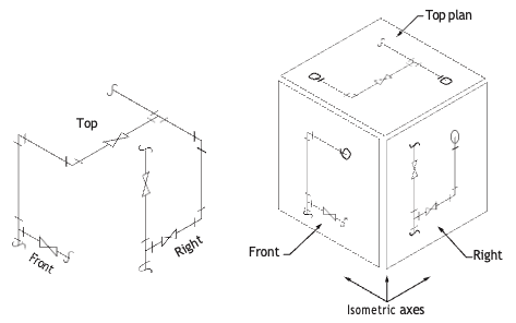
All the piping connected to a fitting is in the same plane. This determines how the fitting is drawn. The runs and joints are parallel to the edges of the plane. Figure 25 shows two tees on the same vertical pipe. Notice how the joints are drawn differently because the horizontal parts are in different planes. The upper tee faces the left, but the lower tee faces the back.
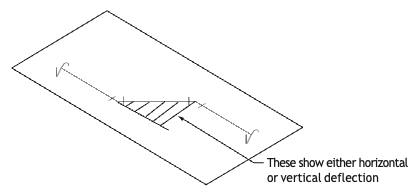
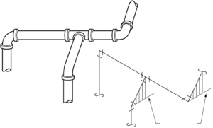
Piping runs that are not parallel to the isometric axes will not be to scale. Two examples of lines that will not be to scale are the 45° run from one end of a 45° elbow and the branch of a 45° wye fitting. Such runs are drawn by proper orientation to the isometric axes, and the joint is drawn perpendicular to the pipe it crosses (Figure 26). The pipe between the two 45° elbows is non- isometric, and the joints are perpendicular to the pipe.
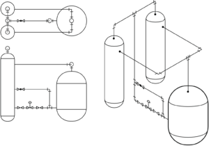
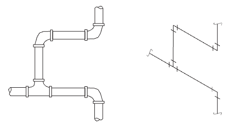
Figures 27 and 28 show objects drawn both orthographically and isometrically. Notice that the isometric drawing is three dimensional and shows height, width and depth in one view. This typically makes isometric drawings easier to interpret than orthographic drawings. Figure 28 contains piping in only one plane, so only the vertical axis and the left-right axis are needed for the isometric drawing. The isometric drawing in Figure 29 is three-dimensional and uses all three isometric axes.
Conversion Between Orthographic and Isometric Drawings
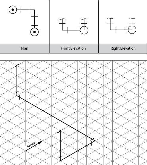
To convert a multi-view orthographic projection to a three-dimensional isometric projection is quite simple. Orient the isometric grid to match the side of the orthographic projection. In this case use the front view.
Remember that the two vertical directions (up and down) are represented by vertical lines. The four horizontal directions (front and back; left and right) are represented by lines at 30° from the horizontal. Plot the line segments at the proper orientation, as shown in the examples.
Example 1
Example 2

Self-Test C-3.6.2: Use Drawing Projections
Complete Self-Test C-3.6.2 and check your answers.
If you are using a printed copy, please find Self-Test C-3.6.2 and Answer Key at the end of this section. If you prefer, you can scan the QR code with your digital device to go directly to the interactive Self-Test.
References
BCcampus. (n.d.). Playlist: Tools and equipment videos. BCcampus MediaSpace. https://media.bccampus.ca/playlist/details/0_3g8xp22x/categoryId/175673 Playlist Details – Trades Access Common Core Line C: Tools and Equipment Videos – BCcampus
BC Industry Training Authority. (2019). Piping trades apprenticeship program: Use Tools and Equipment—Level 1 harmonized [Binder]. Crown Publications, Queen’s Printer for British Columbia. https://www.crownpub.bc.ca/Product/Details/7960000261_S
- Plumber: Competency C-2 Interpret Drawings and Specifications
- Steamfitter: Competency C-2 Interpret Drawings and Specifications
- Sprinkler Fitter: Competency C-2 Interpret Drawings and Specifications
Camosun College. (2019). Line D: Tools and Equipment—Competency D-3: Competency D-3: Read Drawings and Specifications (Rev. ed.) [Learning guide]. BCcampus. https://collection.bccampus.ca/textbook/yxJ3AwTa/
Camosun College. (2015). Trades Access Common Core Competency D-3: Competency D-3: Read Drawings and Specifications. Victoria, B.C.: Crown Publications. Download for free from the B.C. Open Textbook Collection (https://open.bccampus.ca/browse-ourcollection/find-open-textbooks/).
Media Attributions
All figures are sourced from Industry Training Authority (2019) and/or Camosun College (2019) and are used under the Creative Commons Attribution 4.0 (CC BY 4.0) licence unless otherwise noted. Images copyrighted by the BC Industry Training Authority are licensed under a Creative Commons Attribution-NonCommercial-ShareAlike 4.0 (CC BY-NC-SA 4.0) licence.