C-3.3 Describe Piping and Fixture Symbols Used in the Piping Trades
Symbols
In the piping trades, drawings are a universal language. Before any pipe is cut, assembled, or installed, the entire system is communicated through symbols that represent pipes, fittings, valves, and fixtures. These symbols allow designers, plumbers, inspectors, and other trades to understand a piping layout quickly without needing detailed written explanations.
Because every symbol has a specific meaning, using the correct one is essential. A single incorrect symbol on a drawing can lead to wrong materials being ordered, improper installation, or costly delays. For this reason, piping symbols are intentionally simple, standardized, and easy to draw accurately.
This section introduces the different types of piping symbols—single-line, double-line, and symbols that identify specific pipe materials. Understanding these symbols is a foundational skill for anyone working in the piping trades, as they appear in virtually every plan, sketch, schematic, and installation drawing you will encounter.
Single-Line Symbols
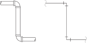
Piping systems are usually drawn with single-line symbols because they are quick and easy to draw yet convey a great deal of information. The single-line symbol represents the centre line of the pipe and fittings as seen from the side. Figure 1 shows the same piping run represented by double- and single-line symbols.
Single-line symbols are often used on drawings:
- when speed of execution is important
- of extensive piping systems that have long runs
- when the size of the piping is less than NPS 12″
- that only show processes or principles of operation (“diagram drawings” or “flow charts”)
- that are produced in order to make materials lists
On single-line drawings, the piping run lengths may or may not be drawn to scale, but the sizes of the valves or fittings are always drawn to scale. The exception is the flow chart.
Double-Line Symbols
A double-line drawing is used when accurate scale and a more realistic appearance are needed. In this method, two lines that are spaced to scale represent both the length of each pipe and its nominal pipe size.
Double-line drawings are usually made for the purpose of giving more detailed information than can be shown on single-line drawings of smaller scale. Many companies use single-line drawings for piping smaller than NPS 12″ and double-line drawings for NPS 12″ pipe and larger.
Double-line symbols may be used for fittings, such as tees and elbows, making them look very real. Valve bodies are often drawn exactly like the single-line symbol and do not look real.
On double-line drawings, flanged and welded fittings and valves are drawn to scale with respect to both fitting run length and the perpendicular flange length. Threaded fitting and valve lengths are scaled only if there are close clearances.
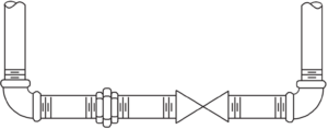
Figure 2 illustrates some of the common symbols used in double-line pipe drawings. Note that threaded fittings are drawn to a close approximation of the actual shape of the fitting. The valve is strictly symbolic.
Due to the more intricate details of double-line drawings, do not use a scale smaller than 1:50 ([latex]\frac{1}{4}\text{"} = 1\text{'} - 0\text{"}[/latex]) unless the pipe sizes are large enough to show up well on the drawing. [latex]\frac{3}{8}\text{"} = 1\text{'} - 0\text{"}[/latex] is the standard process area pipe drawing scale.
Symbols for Pipe Process Type
Letters or dash symbols can be placed in convenient locations along the drawing of a pipe to identify the fluid that it will carry. Table 1 shows some examples. A legend that looks like Table 1 should be added to the drawing to identify the symbols used.
Table 1 Pipes identified for intended fluid
 Piping Break Lines
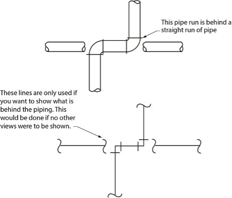
Piping break lines indicate the termination of the drawing of a piping run, although the piping does not end. Break lines are illustrated in Figure 3.

Piping breaks may be used where a pipe runs past the end of a drawing or to show piping that is hidden behind another piping run (Figure 4). When the drawing is complex, as in an isometric drawing of a complete system, the break lines may be omitted. A small gap is used to indicate that the piping run behind does not connect with the piping run in front.
Piping Joints
Some common piping joints include:
- screwed
- welded
- flanged
- soldered
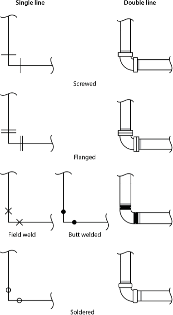
In single-line drawings, a short line has traditionally been used to indicate a screwed pipe joint. It is drawn at right angles (perpendicular) to and centred on the piping run (Figure 5). This symbol is now used for almost any kind of pipe joint in single-line drawings, except that flanged and welded joints may use their own symbols. Figure 5 illustrates the various methods of drawing pipe joints in both single- and double-line forms, using a 90° elbow as an example.
Drawing Views
The appearance of a fitting changes when it is viewed from a different direction. The piping symbols are different for every view to reflect the change in their appearance.
For example, the front view of an elbow and its joining pipes (Figure 6) is at right angles (perpendicular) to both pipes. The symbol is drawn with single lines, and the joints are drawn with short, straight lines. The short, straight line represents the viewed edge of the fitting. The application is the same for both single- and double-line drawings.
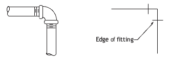
If the elbow is viewed from the right side, the vertical pipe is perpendicular to the line of sight, but the horizontal pipe is viewed on end. The corresponding view symbol represents the vertical pipe by a vertical line and the joint by a short crossing line, as expected.

The end view of the fitting is represented by a circle (Figure 7). The circle is the true appearance of the edge of the fitting. The back of the elbow is shown by the centre line continuing to the centre of the circle.
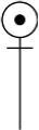
Figure 8 Left view of elbow in Figure 6
The left view is shown in Figure 8. This view faces the pipe and an open end of the fitting, which is represented by a dot at the centre of the circle, as if it were a hole. Again, the circle appears like the true edge of the fitting.
Occasionally, pipes and joints are viewed neither on end nor perpendicular but receding at an angle (usually 45°). In those cases, the symbol for the near edge of the fitting is a curved line (Figure 9). Note that the curve is the true appearance, as if the far edge were obscured by the pipe or fitting.
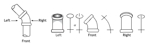
One end of a 90°elbow angled at 45° (Figure 10) will also use the curved symbol on one end.
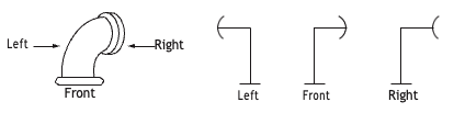
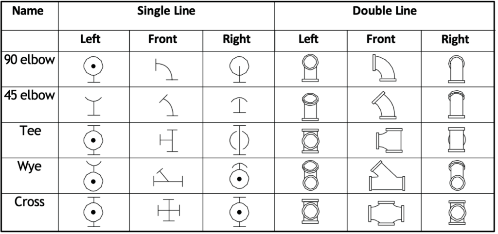
This example of views for drawing fitting symbols should help you recognize the symbols for single-line and double-line drawings presented in Table 2.


Symbols for Valves, Air Eliminators, Pumps and Other Components
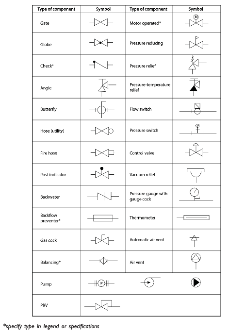
Valves, air eliminators, pumps and other components are generally shown on drawings by their symbols, even when double-line piping drawings are used. Table 5 shows some of the most common symbols.
Check Valves
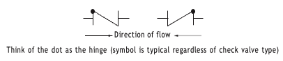
The symbol for a check valve is positioned to indicate the direction of flow (Figure 11). It is important to draw the symbol in the correct position or the diagram could be misinterpreted, leading to the valve being installed incorrectly. The symbols are typically used without the arrows shown in Figure 11, which are shown here to help you understand the correct orientation of the symbol. Specifications or notations on the drawing will indicate what type of check valve is needed (i.e., swing check, lift check, etc.).
These are just a few commonly used symbols for piping fittings, valves and other components. Symbols for other components may be more or less standard or may be modified as required. Such modifications should be labelled with a reference legend that identifies the symbol.
Symbols for Plumbing Fixtures
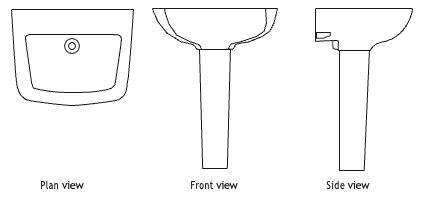
Plumbing fixtures are generally shown on plan and elevation drawings by their actual size and shape according to the drawing scale (Figures 12 to 18). This is required to determine if the fixture location in the building is in compliance with Building Code clearances to walls and other fixtures.
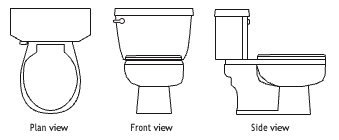
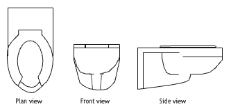
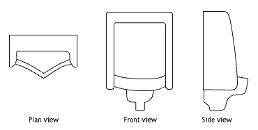
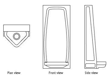
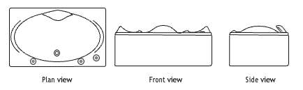
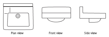
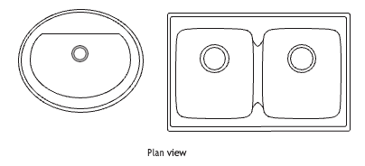
Unlike free-standing fixtures, cabinet-mounted fixtures would only be represented in plan view (Figure 19). In elevation views only the cabinet that houses the fixture would be shown, as the fixture itself is recessed.

Self-Test C-3.3: Describe Piping and Fixture Symbols Used in the Piping Trades
Complete Self-Test C-3.3 and check your answers.
If you are using a printed copy, please find Self-Test C-3.3 and Answer Key at the end of this section. If you prefer, you can scan the QR code with your digital device to go directly to the interactive Self-Test.
References
BCcampus. (n.d.). Playlist: Tools and equipment videos. BCcampus MediaSpace. https://media.bccampus.ca/playlist/details/0_3g8xp22x/categoryId/175673 Playlist Details – Trades Access Common Core Line C: Tools and Equipment Videos – BCcampus
BC Industry Training Authority. (2019). Piping trades apprenticeship program: Use Tools and Equipment—Level 1 harmonized [Binder]. Crown Publications, Queen’s Printer for British Columbia. https://www.crownpub.bc.ca/Product/Details/7960000261_S
- Plumber: Competency C-2 Interpret Drawings and Specifications
- Steamfitter: Competency C-2 Interpret Drawings and Specifications
- Sprinkler Fitter: Competency C-2 Interpret Drawings and Specifications
Camosun College. (2019). Line D: Tools and Equipment—Competency D-3: Competency D-3: Read Drawings and Specifications (Rev. ed.) [Learning guide]. BCcampus. https://collection.bccampus.ca/textbook/yxJ3AwTa/
Camosun College. (2015). Trades Access Common Core Competency D-3: Competency D-3: Read Drawings and Specifications. Victoria, B.C.: Crown Publications. Download for free from the B.C. Open Textbook Collection (https://open.bccampus.ca/browse-ourcollection/find-open-textbooks/).
Media Attributions
All figures are sourced from Industry Training Authority (2019) and/or Camosun College (2019) and are used under the Creative Commons Attribution 4.0 (CC BY 4.0) licence unless otherwise noted. Images copyrighted by the BC Industry Training Authority are licensed under a Creative Commons Attribution-NonCommercial-ShareAlike 4.0 (CC BY-NC-SA 4.0) licence.