C-2.4 Measuring Electricity
Test Equipment
When you see lightning, you are not seeing electricity itself, but the release of electrical energy in the form of light. Electricity cannot be seen directly, so when an electrical circuit is not operating correctly, and unless you can see loose or damaged wire connections, you will need instruments that check for the absence or presence of electricity to discover what is wrong.
To measure the effect of electricity, you must use an electrical meter. As electrical quantities vary, so do their effects on the meter. Meters come in a variety of designs, and you must be familiar with some of the most common types used during installation and servicing of hydronic equipment.
Because some electrical effects are very small, most meters are built with delicate operating mechanisms. Meters can be damaged easily, so they must be stored, handled, and used with great care.
Types of Electrical Meters
The most common types of electrical meters are:
- Ammeters
- Voltmeters
- Ohmmeters
For economic reasons, you will most likely not have three separate meters but one unit that combines the functions of all three. This device is referred to as a multimeter. A multimeter is able to measure volts, ohms, and low values of current (amps). Regardless of the type of meter used, it must be connected correctly to the circuit being tested to obtain accurate readings.
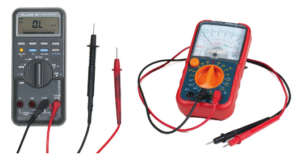
The two major types of meters, analogue and digital (Figure 1), perform the same functions but look different. The main difference is in the display unit. The key features are very similar and will be explained below.
Analogue Multimeters (VOMs)
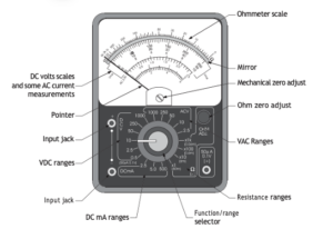
Analogue multimeters, also called volt-ohm-milliammeters (VOMs) (Figure 2), are older-style meters that use a moving needle to display readings. While they are not commonly used in the piping trades today, it is important to be aware of them, as you may still encounter them in older equipment or training materials.
VOMs measure voltage, current, and resistance, similar to modern digital multimeters. However, they require careful handling because the needle mechanism is delicate, and incorrect connections—especially when measuring direct current (DC)—can damage the meter. They must also be properly zeroed before use and read from directly in front to avoid parallax error.
In most modern applications, digital multimeters are preferred because they are easier to use, more accurate, and less prone to damage.
Measuring Voltage Using a VOM
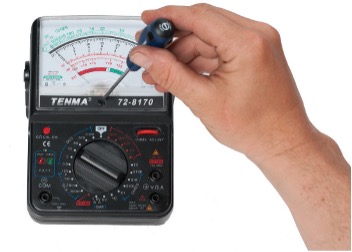
When performing any tests, it is important to first confirm that the meter is adjusted and working properly. Before using a meter on AC or DC voltage, zero the meter, as shown in Figure 3. Use a blade screwdriver to position the needle directly over the “0” on the left of the scale.
Next, check the meter’s operation by exposing it to a known source of voltage. Remember to correctly polarize the leads if using a DC voltage such as a battery. This is done by performing a “tap” or “flash” test: connect one meter lead to a test point and, with the function switch set to a higher DC voltage scale than the source being tested, tap the other lead to the second test point. This will cause the needle to deflect. If the deflection is in the wrong direction, simply reverse the position of the test leads. Then take a reading and confirm that it matches the expected value.
If you are checking the meter using an AC source, such as a wall receptacle, set the function switch to the highest AC setting and insert the two leads into the receptacle’s jacks, in no specific position. Polarity does not matter for AC. Remember that the meter will automatically polarize the signal so the needle will deflect in the correct direction. If the reading matches the expected value, the meter is ready for use.
When measuring voltage, the meter is connected in parallel with the circuit being tested. This means no wires need to be removed from the circuit. The voltmeter reads the difference between the two test points.
Think of a voltmeter as operating in “subtraction mode”—it measures the difference in voltage between its two leads. This can create a safety hazard if misunderstood. For example, measuring across a closed switch in a live 120 V circuit may show 0 V, even though the circuit is energized.

Always verify circuit conditions before touching components.
Summary of using a VOM to test voltage:
- Zero the needle.
- Check the meter for operation first on a known voltage source.
- Start with the highest voltage scale first.
- Polarize the test leads if testing a DC circuit (“flash test”).
- Connect the meter in parallel with the live circuit being tested.
- Interpret the reading and select a lower scale, if possible, for more accuracy.
Measuring Current Using a VOM
Using a VOM to measure current (amperage) requires connecting the meter in series with the circuit being tested. This means disconnecting a conductor and inserting the meter between the wire and the terminal. This makes the meter part of the circuit, so all current flowing through the circuit also flows through the meter, which creates a limitation in that the meter leads must be heavy enough to allow current flow, which causes heat, without burning up. Because of this, meter leads must carry current safely. Most multimeters are limited to measuring low current (milliamps) when using test leads.
Summary of using a VOM to test DC milliamperage:
- De-energize the circuit to be tested.
- Disconnect a wire and insert the meter in series with the circuit, observing the correct polarity of the test leads.
- Set the meter to the highest DC milliamp range.
- Energize the circuit and interpret the reading.
- Switch to a lower scale, if possible, for more accuracy.
- De-energize the circuit before removing the meter.
- Re-connect the circuit wiring and re-energize the circuit.
Digital Multimeters
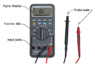
All digital multimeters (DMMs) Figure 4) have similar features and are used in the same way as VOMs, except that the display is a numbered readout of digits rather than a pointer moving over numbered scales. Some digital meters have a function switch that must be set on the appropriate range just like with a VOM, whereas others are self-ranging or auto-ranging and are intuitive to the type of current or voltage that they are being exposed to. They do not differ from the VOMs in their inability to measure units of amperage and are likewise restricted to milliamps of current, but they are easier to read and generally more accurate than analogue meters.
Watch the following video by Afrotechmods (2010) on YouTube titled “THE BEST Multimeter tutorial (HD)” [4:35].
If you are using a printed copy, you can scan the QR code with your digital device to go directly to the video: THE BEST Multimeter tutorial (HD).

As mentioned, using a digital meter involves little or no interpretation as to the reading being registered and, for this reason, most technicians favour them over the VOM. One drawback of the DMMs is that they require a battery in good condition for all readings, whereas the analogue variety requires only a battery for resistance/continuity readings. One advantage of the DMMs is that they often have the ability to read current in the range of microamps. An analogue meter would have to be specifically designed for this range only.
Measuring Current Readings Above the Milliamp Range
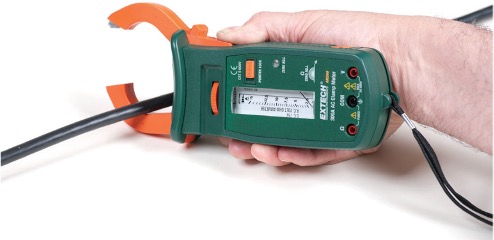
Current readings above the milliamp range are taken with a clamp-on ammeter (Figure 5). These devices are usually digital and can be a stand-alone ammeter or can perform all the functions of a multimeter with the added capability of reading full amps. When measuring amperage, the spring-loaded jaws are opened and clamped around a single conductor in the circuit. Current running through a conductor creates an electromagnetic field around it, and the strength of the field is measured by the device and translated into a current reading. It is important to realize that the current flow through two conductors in a circuit can’t be read together. In a two-wire circuit, the direction of the two electromagnetic fields is opposite to each other and will cancel each other out if the meter is clamped around both wires at once.
Measuring Resistance Using a VOM
A VOM can be used to measure resistance or continuity in a circuit. In the same fashion as in testing for current flow, the meter must be installed in series with the circuit or individual component being tested, with one exception: the circuit must not be live!
A battery inside the meter will try to push a small amount of current out through one of the leads and expects to get it back through the other lead. The amount of resistance to this flow of current, measured in ohms, will be read on the topmost scale of the meter. If there is no resistance at all, the needle should move to the far right side of the scale over the “0” mark, indicating no resistance in ohms. If the circuit is completely broken, or open, the needle will not move off the left side of the scale, where the symbol for infinity (∞) exists, meaning there is an infinite amount of resistance.
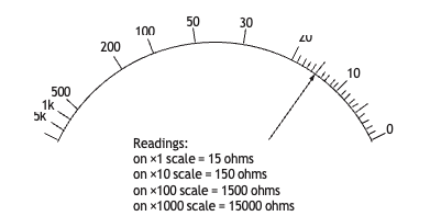
The ohms scale is therefore said to be non-linear in that halfway along the scale is not half of an infinite amount of resistance, because this number cannot be estimated. Because there is only one scale to interpret, it is important to note the reading on the scale and adjust it according to the function switch position. For example, with the function switch set to “×10” a reading of 15 on the scale would indicate a reading of [latex]15 \times 10 = 150 \text{ ohms } (150 \space \Omega)[/latex]. The same reading with the switch set to the 1K scale would indicate a reading of [latex]15 \times 1,000 = 15,000 \text{ ohms } (15,000 \space \Omega)[/latex] (Figure 6).
The ohmmeter must be zeroed before it can be used accurately (Figure 7). To do this, set the function switch to any of the ohms range settings and touch both leads together. The pointer should move to the far right side of the ohms scale and hover directly over the “0” mark. If it is off the mark to either side, use the Ohms Zero dial to correct the reading. The ohmmeter is now ready for use.
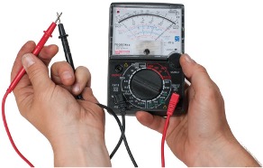
Measuring continuity is similar to measuring ohms in that the power to the circuit must be turned off. The multimeter sends out a small electrical current, and if it makes it through the circuit back to the meter, the circuit has continuity. Some meters emit an audible “beep” to indicate a continuous circuit.
It is important to also return the function switch to the “Off” position (if available) or to the highest AC volts range to ensure the battery doesn’t drain during storage.
Summary of using a VOM to measure resistance:
- De-energize the circuit or component to be tested.
- Make sure that current from the meter can only flow through one circuit if there are two parallel circuits connected.
- Set the function switch to the highest range and “zero” the meter.
- Touch the meter leads across the circuit or component and interpret the reading.
- Move to a lower range for more accuracy.
- When finished, turn the meter to “Off” or to the highest AC volts range.
Proper Handling and Storage
The proper care of test equipment and instruments is of utmost importance, whether they are analogue or digital. The length of time an instrument retains its original usefulness and accuracy depends largely upon the care it receives in the hands of the user. These precautions apply equally to digital and analogue meters:
- Do not drop any meter.
- Do not overload any meter. When in doubt, use a high range that you know will not be overloaded. You can always switch to a lower range, if necessary.
- Do not tamper with precision instruments. Let a competent instrument repair person service precision instruments.
- Before you connect a meter to a circuit, ensure that the range switch is set to an appropriate position.
- Carefully check circuit connections before applying power to meters.
Safety
Although electricity is vitally important in carrying out our daily functions, it can also be deadly if handled carelessly. One-tenth of an ampere of alternating current flowing through a vital organ can be fatal. Take safety precautions whenever working with electricity. Keep in mind the following precautions:
- Never cut off the third prong of a grounded plug. A grounded plug makes power tools and appliances safer to operate.
- Never touch any wire without making sure that it is not a live wire.
- Never turn an electrical appliance on or off while your skin is wet. Dry skin has a resistance of more than 100 000 ohms; wet skin’s resistance drops to 1000 ohms.
- A current flow of 0.02 amperes is the maximum that a muscle can carry and still pull away from a conductor.
- Always disconnect the master switch or main disconnect before working on an electrical line or circuit.
- Always unplug an electrical appliance before working on it. Simply turning it off does not necessarily make it safe.
- Replace worn appliance cords.
- Unplug cords by pulling on the plug—not on the cord.
- Never turn an appliance on or off while standing in or touching a wet area.
- Notify the proper authorities whenever you find broken electrical wiring touching the ground. Do not attempt to touch the wire with another object.
- When working on electrical equipment that is live, try to use one hand only. If a person is shocked using one hand, current will probably flow through the hand and down through the feet. If a shock hits both hands, the electrical path would be through the heart, which could be fatal.

Self-Test C-2.4: Measuring Electricity
Complete Self-Test C-2.4 and check your answers.
If you are using a printed copy, please find Self-Test C-2.4 and Answer Key at the end of this section. If you prefer, you can scan the QR code with your digital device to go directly to the interactive Self-Test.
References
Afrotechmods. (2010, March 18). The best multimeter tutorial (HD) [Video]. YouTube. https://www.youtube.com/watch?v=bF3OyQ3HwfU
BCcampus. (n.d.). Playlist: Tools and equipment videos. BCcampus MediaSpace. https://media.bccampus.ca/playlist/details/0_3g8xp22x/categoryId/175673 Playlist Details – Trades Access Common Core Line C: Tools and Equipment Videos – BCcampus
BC Industry Training Authority. (2019). Piping trades apprenticeship program: Use Tools and Equipment—Level 1 harmonized [Binder]. Crown Publications, Queen’s Printer for British Columbia. https://www.crownpub.bc.ca/Product/Details/7960000261_S
- Plumber: Competency O-1 Use the Principles of Electricity
- Steamfitter: Level 2 Competency K-1 Use the Principles of Electricity
- Sprinkler Fitter: Competency C-1 Use Mathematics and Science
Camosun College. (2019). Line D: Tools and Equipment—Competency D-2: Apply Science Concepts to Trades Applications (Rev. ed.) [Learning guide]. BCcampus. https://collection.bccampus.ca/textbook/qFKGAJ78/
Camosun College. (2015). Trades Access Common Core Competency D-2: Apply Science Concepts to Trades Applications. Victoria, B.C.: Crown Publications. Download for free from the B.C. Open Textbook Collection (https://open.bccampus.ca/browse-ourcollection/find-open-textbooks/)
Camosun College. (2015). Line E – Electrical fundamentals competency E-1: Describe the Basic Principles of Electricity. BCcampus.
https://collection.bccampus.ca/textbook/Nf7jVbAg/
Camosun College. (2015). Line E – Electrical fundamentals competency E-2: Identify common circuit components and their symbols. BCcampus.
https://collection.bccampus.ca/textbook/fGcTBtJh/
Camosun College. (2015). Line E – Electrical fundamentals competency E-3: Explain Wiring Connections. BCcampus.
https://collection.bccampus.ca/textbook/qV9cMUkU/
Camosun College. (2015). Line E – Electrical fundamentals competency E-4: Use Multimeters. BCcampus. https://collection.bccampus.ca/textbook/EnCFy7eD/
Media Attributions
All figures are sourced from Industry Training Authority (2019) and/or Camosun College (2019) and are used under the Creative Commons Attribution 4.0 (CC BY 4.0) licence unless otherwise noted. Images copyrighted by the BC Industry Training Authority are licensed under a Creative Commons Attribution-NonCommercial-ShareAlike 4.0 (CC BY-NC-SA 4.0) licence.
A complete path that allows electricity to flow from a power source, through wires and devices, and back to the source. (Section C-2.2)
A device used to check and measure electricity in a circuit, including voltage, current, and resistance. (Section C-2.4)
A tool that measures how much electrical current is flowing in a circuit. (Section C-2.4)
A tool that can measure voltage, current, and resistance. (Section C-2.4)
The flow of electricity (electrons) through a wire or circuit. (Section C-2.2)
(volt-ohm-milliammeters); A meter that uses a moving needle to show a reading. (Section C-2.4)
The pressure that pushes electricity through a circuit. (Section C-2.1)
A measure of how much a material slows down electric flow. (Section C-2.1)
Electric current that flows in one direction only, like the electricity from a battery. (Section C-2.1)
A reading mistake that happens when you look at a meter needle from the wrong angle instead of straight on, causing the value to appear higher or lower than it really is. (Section C-2.4)
A method used to check a meter by briefly touching a lead to a voltage source to see if the needle moves in the correct direction. (Section C-2.4)
The arrangement of positive and negative connections in a circuit, which determines the direction electricity flows; the correct way to connect meter leads to positive (+) and negative (−) points so the meter reads properly. (Section C-2.4)
A way of connecting a meter where it measures across two points without breaking the circuit. (Section C-2.4)
A measuring device used to check the voltage (electrical pressure) between two points in a circuit. (Section C-2.2)
A way of connecting a meter so that electricity must flow through the meter as part of the circuit, allowing all the electrical current to flow through it before moving on. (Section C-2.4)
A unit used to measure small electrical currents; 1 milliamp equals 0.001 amps; small amounts of electrical current measured by a meter, where one milliamp equals one-thousandth of an amp. (Section C-2.4)
A tool that measures electrical values and shows the results as numbers on a screen. (Section C-2.4)
(or self-ranging); A feature of a meter that automatically selects the correct measurement range for the value being tested, so the user does not need to set it manually. (Section C-2.4)
A tool that measures current by clamping around a wire without touching it directly (Section C-2.4)
An invisible force around a wire when electricity flows through it. (Section C-2.4)
When electricity can flow through a circuit without a break. (Section C-2.4)
A unit used to measure resistance in a circuit. (Section C-2.2)
A tool that measures electrical resistance, or how much something opposes the flow of electric current. (Section C-2.4)
To set a meter to a starting point of zero by adjusting it before use, so measurements are accurate. (Section C-2.4)