C-2.2 Electrical Circuits
Electrical circuits operate using three fundamental concepts: voltage, current, and resistance. These concepts describe how electrical energy is supplied, how it flows, and how it is controlled within a circuit. Understanding these three ideas is essential before working with any powered equipment or electrical components in the piping trades.
Voltage, Amperage and Resistance
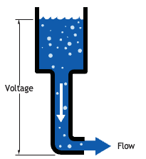
To illustrate the three concepts involving an electrical circuit, consider a tank filled with water to a certain level as an analogy. At the bottom of this tank, there is a hose. If the hose is capped off, there will be head pressure available due to gravity but no flow will occur unless the cap is removed. This available pressure can be compared to voltage in an electrical circuit (Figure 1).
Voltage
Voltage is the electrical pressure or potential created by one of the six methods mentioned earlier: friction, pressure (piezoelectricity), heat (thermoelectric effect), light (photoelectric effect), chemical action, and magnetism (electromagnetic induction). This pressure is needed to push electrons through a circuit. One coulomb of electrical charge is defined as 6.28 quintillion (6.28 × 10¹⁸) electrons, and 1 volt is defined as the electrical pressure needed to force 1 coulomb of charge through 1 ohm of resistance in 1 second. Voltage is the difference in potential between two points in a circuit, and without a source of voltage there can be no current flow.
Amperage
As electrons flow through a conductor, their quantity can be measured. One method of measuring electron flow would be to select a single point on a conductor and count the electrons that pass that point. Since electrons are extremely small, it would be impractical. Instead, electron flow (or current) is measured in large units called amperes (or amps). One ampere is 1 coulomb of charge passing a given point in a circuit in 1 second. It is the flow of current (amperage) that produces work in a circuit. Current must flow in order for lights to light or motors to turn.
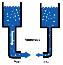
In our illustration, the amount of water flowing through the hose from the tank can be compared to current (Figure 2). The higher the water level, the higher the pressure and the higher the flow rate of water through the hose. A larger hose also allows a higher flow rate. With water, we measure flow as volume of water flowing through the hose over a certain period of time, usually expressed in gallons per minute or litres per second. Conductors (wires) in an electrical circuit are sized on their ability to carry amperage without causing excessive heat build-up.
Resistance
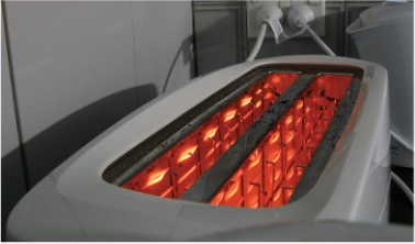
Resistance is generally associated with a load, a basic component of an electric circuit that converts electricity into work. As electrons flow through a conductor, they have a tendency to crowd and push other atoms and electrons. This crowding is minimal and causes little resistance in the conductor. However, a load acts much like a funnel, in that it causes a greater crowding of the electrons and restricts flow. This resistance to flow creates heat as a byproduct, and in the case of a toaster or electric kettle this heat is desirable (Figure 3). However, when electricity is converted to light or mechanical energy (such as in a light bulb or motor), heat is an undesirable byproduct. Conductors must be sized to minimize this heat buildup. Resistance to current flow is measured in units called ohms. In an AC circuit, an additional factor called impedance opposes electron flow. Impedance is also measured in ohms. For the sake of ease, we will use the term resistance to describe impedance in an AC circuit.
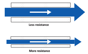
Consider two water tanks: one with a narrow pipe and one with a wide pipe. A wider pipe can transport more volume than a narrow pipe under the same pressure. The narrow pipe “resists” the flow of water through it even though the water is at the same pressure as in the tank with the wider pipe (Figure 4).
Ohm’s Law
In 1827, German physicist Georg Simon Ohm discovered that there is a calculable relationship between electrical pressure, resistance, and current flow in any circuit, and his published theory is called Ohm’s law. Stated as an equation, depending on which value is unknown, Ohm’s law can be expressed in three variations:
[latex]\quad\text{E} = \text{I} \times \text{R}\\ \quad\text{R} = \frac{\text{E}}{\text{I}}\\ \quad\text{I} = \frac{\text{E}}{\text{R}}[/latex]
where
[latex]\quad\text{E} = \text{electromotive force (EMF) measured in volts}[/latex]
[latex]\quad\text{I} = \text{intensity of current measured in amperes or amps}[/latex]
[latex]\quad \text{R} = \text{resistance measured in ohms}[/latex]
The abbreviations for each are V for volts, A for amps and the Greek symbol Ω (omega) for ohms. The omega symbol is used instead of the letter O, which could cause confusion if numbers precede the symbol.
Ohm’s law is commonly presented as a learning triangle (Figure 5) in order to make the relationship between the three electrical entities easier to understand.
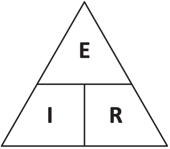
Ohm’s law states that it takes 1 volt to push 1 ampere through 1 ohm of resistance and is a useful tool to assess a circuit and find unknown values.
Watch the following video by Tradestutor (2020) on YouTube titled Ohms law quick and easy [4:17].
If you are using a printed copy, you can scan the QR code with your digital device to go directly to the video:
Ohms law quick and easy

Ohm’s Law Put to Use
Example 1.
[latex]\quad\text{A 12 V battery pushes 3 A of current through a circuit. What is the resistance found in this circuit?}[/latex]
Solution.
[latex]\quad\text{The unknown value is R, resistance.}[/latex]
[latex]\quad\text{Therefore R} = \frac{\text{E}}{\text{I}}[/latex]
[latex]\quad\text{R} = \frac{12 \text{V}}{3 \text{A}}[/latex]
[latex]\quad\text{Resistance} = 4 \space \Omega[/latex]
Example 2.
[latex]\quad\text{Given a circuit with a resistance of 10 Ω, an EMF of 24 V, what is the current flow?}[/latex]
Solution.
[latex]\quad\text{The unknown value is I, amperage.}[/latex]
[latex]\quad\text{I} = \frac{\text{E}}{\text{R}}\\ \quad\text{I} = \frac{24\text{ V}}{10 \space \Omega}\\ \quad\text{I} = 2.4 \text{ A}[/latex]
Example 3.
[latex]\quad\text{If a circuit has a current flow of 2 amps and the resistance is 20 Ω, what is the pressure in volts?}[/latex]
Solution.
[latex]\quad\text{The unknown value is E, voltage.}[/latex]
[latex]\quad\text{E} = \text{I} \times \text{R}\\ \quad\text{E} = 2\text{ A} \times 20 \space \Omega\\ \quad\text{E} = 40 \text{ V}[/latex]
Power
Voltage potential pushes electron flow though a load that changes electrical energy into other forms of energy, such as kinetic energy (in a motor) or heat and light (in a lamp). This work performed by the load is described as power (P) and measured in watts (W).
Power can be expressed as:
[latex]\quad\text{P} = \text{E} \times \text{I}\\ \quad\text{E} = \frac{\text{P}}{\text{I}}\\ \quad\text{I} = \frac{\text{P}}{\text{E}}[/latex]
Where:
[latex]\quad\text{E} = \text{electromotive force, volts}\\ \quad\text{I} = \text{intensity of current, amps}\\ \quad\text{P} = \text{power, watts}[/latex]
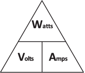
These relationships are often shown using a Watt’s law triangle (Figure 6), which helps visualize the relationship between voltage, current, and power, and makes it easier to determine unknown values.
Power Calculation Put to Use
Example 1.
[latex]\quad\text{What size [pb_glossary id="5466"]fuse[/pb_glossary] is appropriate for a 96 W bulb in a 12 V DC system?}[/latex]
[latex]\quad\text{I} = \frac{\text{P}}{\text{E}}\\ \quad\text{I} = \frac{96\text{ W}}{12 \text{ V}}\\ \quad\text{I} = 8 \text{ A}[/latex]
The fuse would need to be rated for more than 8 amps.
Example 2.
[latex]\quad\text{How much power would a soldering gun produce if it uses 6 A in a 120 VAC circuit?}[/latex]
[latex]\quad\text{P} = \text{E} \times \text{I}\\ \quad\text{P} = 120\text{ V} \times 6 \text{ A}\\ \quad\text{P} = 720 \text{ W}[/latex]
Example 3.
[latex]\quad\text{Here we see how Ohm’s law and the power calculation can be used together.}[/latex]
[latex]\quad\text{What is the correct theoretical resistance of a hot water tank element with a power}\\ \quad\text{rating of 4,500 W in a 240 VAC system? Note: this info, Watts and VAC, is given on}\\ \quad\text{the name plate of an element.}[/latex]
[latex]\quad\text{I} = \frac{\text{P}}{\text{E}}\\ \quad\text{I} = \frac{4,500\text{ W}}{240 \text{ V}}\\ \quad\text{I} = 18.75 \text{ A}\\ \quad\text{R} = \frac{\text{E}}{\text{I}}\\ \quad\text{R} = \frac{240\text{ V}}{18.75\text{ A}}\\ \quad\text{R} = 12.8 \space \Omega[/latex]
Summary
Electricity flowing through a conductor can be compared to water flowing through a hose. The voltage that forces electrons to flow through the conductor is comparable to the water pressure or psi that forces water through the hose. The amperage is the number of electrons that pass through the conductor and compares to the number of gallons of water that pass any given point over time. Resistance is similar to the friction between the water and the walls of the hose. In any electrical circuit, it is the electrical pressure or voltage from the source that causes electrons to flow, and in most circuits, this voltage is kept fairly constant. The amount of electron flow or amperage depends upon the resistance in the circuit. If the total resistance in the circuit is high, then the amperage will be low, and vice versa. If at any time the resistance of a given circuit is changed, then the amperage will also change.
Using Electric Current
For electric current to be usable, it must be able to travel from the source through the conductor to the load and then back to the source. As mentioned earlier, the source produces one of two basic types of electric current: alternating current (AC) or direct current (DC). Each has unique properties that make it more desirable than the other under certain circumstances.
Direct current (DC)
As mentioned earlier, chemicals, heat, pressure, light, and friction are all causes of direct current or DC voltage.
A battery is a common source of direct current (DC) (Figure 7). A battery will always have two poles or terminals: one negative and one positive. A chemical reaction inside the battery between the anode and the cathode causes electrons to move through an electrolyte (acid or alkali) to the negative terminal, giving it a negative (–) electrical charge (creating electrical flow). The other terminal has a corresponding lack of electrons, making its charge positive (+). If a wire is connected from a negative terminal to a light bulb and then to a positive terminal, electrons will flow through the conductors from the negative terminal to the positive terminal through the bulb, and the bulb will light.
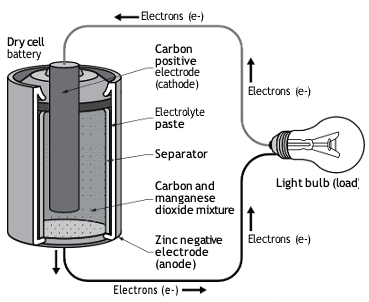
Although there are conflicting theories in the field, the most popular theory is that electron flow in a DC circuit is always negative-to-positive, and this direct current flows constantly in one direction until the circuit is broken or the source stops supplying electrons.
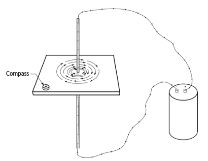
Another characteristic of any electron flow can be demonstrated using a DC power source, a square piece of cardboard, and some iron filings (Figure 8). A hole is cut through the centre of the cardboard. A wire is run from one terminal of a battery, through the hole in the cardboard, and back to the other battery terminal. Iron filings are lightly scattered on the cardboard, and the cardboard is gently tapped. The filings will arrange themselves in concentric circles on the cardboard around the conductor. This illustrates the presence of a magnetic field around the conductor whenever current flows through it. The iron filings align themselves with the magnetic field that exists while current flows. If the wires are disconnected, the magnetic field collapses and disappears, and the filings will no longer be arranged in any pattern. This illustrates the concept that a magnetic field is associated with any movement of electrons.
Alternating Current (AC) and Electromagnetic Induction
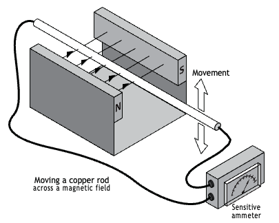
Alternating current (AC) is a current that flows through a conductor in one direction for a split second and then in the opposite direction for a split second. Current alternates because of the generation techniques used at the power plant. The power of steam or water spins a loop of wire within an external magnetic field. Current is produced in a conductor when it is moved through a magnetic field because the magnetic lines of force are applying a force on the free electrons in the conductor and causing them to move (Figure 9). This process of generating current in a conductor by placing the conductor in a changing magnetic field is called induction. It is called induction because there is no physical connection between the conductor and the magnet. The current is said to be induced in the conductor by the magnetic field.
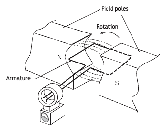
One requirement for this electromagnetic induction to take place is that the conductor, which is often a piece of wire, be perpendicular to the magnetic lines of force to produce the maximum force on the free electrons. The direction in which the induced current flows is determined by the direction of the lines of force and by the direction in which the wire is moving in the field. If an AC current is fed through a piece of wire, the electromagnetic field that is produced is constantly growing and shrinking due to the constantly changing current in the wire.
This growing and shrinking magnetic field can induce electrical current in another wire that is held close to the first wire. The current in the second wire will also be AC and, in fact, will look very similar to the current flowing in the first wire. It is common to wrap the wire into a coil to concentrate the strength of the magnetic field at the ends of the coil. Wrapping the coil around an iron bar will further concentrate the magnetic field in the iron bar. The magnetic field will be strongest inside the bar and at its ends (poles).
Here in North America, the generators that create alternating current might spin at a rate of 3,600 rpm (revolutions per minute), whereas in Europe it’s slightly slower, perhaps 3,000 rpm.
As the coil moves through its rotation, it will experience a buildup and dropoff of current in a positive polarity through 180 degrees and then a buildup and dropoff in the other half-rotation but in a negative polarity. In North America, AC typically operates at 60 hertz (Hz), meaning the current changes direction 60 times per second, whereas in Europe, the frequency is 50 Hertz. An estimated 95% of all electricity generated and distributed in North America is alternating current.
Single-Phase Power Supply
Single-phase electric power refers to the distribution of alternating current electric power using a system in which all the voltages of the supply vary in unison. Single-phase distribution is used when loads are mostly lighting and heating, and with a few large electric motors. Single-phase power comprises two independent voltages that are carried on two separate conductors or hot lines.
The two hot lines are called Line 1 and Line 2. Single phase is typically found in residential and small commercial applications. Single-phase AC supply voltage is commonly stepped from three-phase distribution to 120 or 240 VAC at point of use.
Three-Phase AC Power Supply
Three-phase AC electrical power refers to a type of electrical power distribution in which three or more energized electrical conductors are carrying alternating currents. Examples of three- phase power systems are industrial applications and power transmission. Three-phase power supply is used to power large motors and other heavy loads. A three-phase system is generally more economical than equivalent single-phase systems at the same voltage.
Three-phase power comprises three independent voltages that are carried on three separate conductors. The three hot lines are called Line 1, Line 2, and Line 3. Like single phase AC, three phase AC uses transformers, described as delta and/or wye windings that provide multiple step-up or -down options. Three-phase power is typically found in commercial and industrial applications. Three phase AC supply is commonly stepped to 208 VAC at point of use.
Advantages of Using Alternating Current
For generating and distributing large quantities of electrical energy, alternating current is used rather than direct current. There are several reasons for this:
- Alternators can be manufactured with much higher voltage and power ratings than DC generators. In North America, large alternators commonly generate electrical voltages as high as 13,800 volts. The output windings called the armature can be mounted on the stationary part of the machine, and the magnetic field can be made to rotate by mounting it on the rotor. The current produced by an AC generator (alternator) need not pass through a set of commutators and brushes. It is the commutator and brushes in a DC generator that limit the maximum voltage and power rating of the machine.
- Alternating voltages can be easily stepped up and down. Transformers allow the alternating voltages to be stepped up at the source so that they can be transmitted long distances at higher voltages with lower currents. This reduces both line drop and line loss. At the load end, the transformers can step down the voltage to a lower, safer voltage for utilization. These transformers have efficiencies in the range of 95% to 99%. With DC voltages, this process is much more difficult and much less efficient.
- AC motors and controls are generally smaller, simpler, cheaper and more reliable than DC motors with similar ratings. Because AC induction motors do not require brushes, they are much more reliable. The brushes required in a DC motor need a lot of maintenance. Also, the initial cost of an AC induction motor is lower than that of a comparable DC motor.
Advantages of Using Direct Current
It is easy to understand how these advantages make alternating current a less expensive, more efficient and more reliable way of transmitting energy over long distances. However, there are some situations in which the use of direct current is a better choice. Sometimes it is the only choice.
- Direct current is required to produce the magnetic fields for alternators and synchronous motors. An alternating current would produce a field with poles that constantly reverse.
- Electrochemical processes such as electroplating and battery charging require DC voltages.
- High-intensity light sources that use carbon arcs require direct current.
- Many manufacturing processes require very precise speed control of motors. In the past, it was not possible to get the same speed accuracy with AC motors as with DC motors. However, with the advent of variable-frequency drives, this is changing. Many applications that once required DC motors and controls are now using AC motors and variable-frequency drives.
- The use of DC traction motors on such equipment as electric trains and mining rock-trucks eliminates the need for transmissions, clutches and drive shafts.
A Simple Circuit
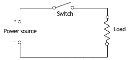
A simple circuit (Figure 10) contains four basic components:
- A power source: Provides the voltage needed to push current through the circuit.
- Conductors: Wires or pathways that allow current to flow.
- A control device: Usually a switch that opens or closes the circuit.
- A load: A device with resistance that performs work, such as producing heat, light, or motion.
In this type of circuit, the electrical energy supplied by the power source is used by the load and converted into useful work—for example, heating a toaster, lighting a bulb, or turning a motor.
Switches
Switches are used to control a load in a circuit. A switch is a device that simply opens or closes an electrical circuit. A switch has at least two positions: open or closed. When a switch is open, no electricity can flow through it. An open switch will de-energize the load. When a switch is closed, electricity can flow through the circuit and energize the load. Circuits are called open or closed in conjunction with switches being opened or closed. Open means OFF, and closed means ON.
Most switches have two parts: a throw and a pole (Figure 11). The throw is the part of a switch that remains stationary. The pole is the part of the switch that moves to open or close the switch. When the pole is touching the throw, the switch is closed. Switches are described by the number of poles and throws they have. To throw a switch, the pole is moved to another position. Thus, a throw is a position of the pole. The simplest switch is a single pole, single throw (SPST) switch. This means it has one pole (moving mechanism) and one throw (position) that the pole can make contact with. An example of an SPST switch would be the switch that turns your bedroom light on or off.
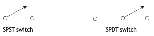
If another contact is added to an SPST switch, it becomes a single pole, double throw (SPDT) switch. The pole can be thrown to one of two positions to energize one of two different circuits or loads. An example of an SPDT switch would be a three-way switch that operates a hallway light fixture. One of these switches at either end of the hallway can turn the light on or off.
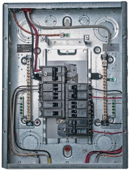
Some household appliances such as electric ranges and water heaters require 240 volts AC. In this case, two circuits are connected to the two “busbars” within an electrical panel, each with 120 volts of potential but each being 180 degrees “out of phase” from each other. Electrical panels are designed so that two breakers installed side-by-side will each make contact with the different busbars (Figure 12). In this method, the voltages are added together and fed to the same piece of equipment through a cable that will have each of these voltages carried by a different-coloured insulated conductor, think a range fed with Lines 1 and 2 for 240 VAC. Typically, the colours of these two “hot” wires are red and black. The two breakers supplying the circuit will have their poles tied together for safety. This is to prevent one circuit from being de-energized without interrupting voltage to the other. Because the two switches are operated simultaneously and are either open or closed, the breaker would be categorized as double pole, single throw (DPST) (Figure 13).
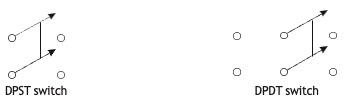
If another throw is added to the DPST switch, it becomes a double pole, double throw (DPDT) switch. Now the poles can make contact in two positions, such as might be found in a circuit that has a forward/reverse operation of a 240 volt piece of equipment.
If a single pole can be thrown so that it will make contact with any one of a number of contacts, it is called a rotary switch (Figure 14). An example of a rotary switch might be one that is used in an audio store to enable one set of speakers at a time to be listened to.
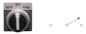
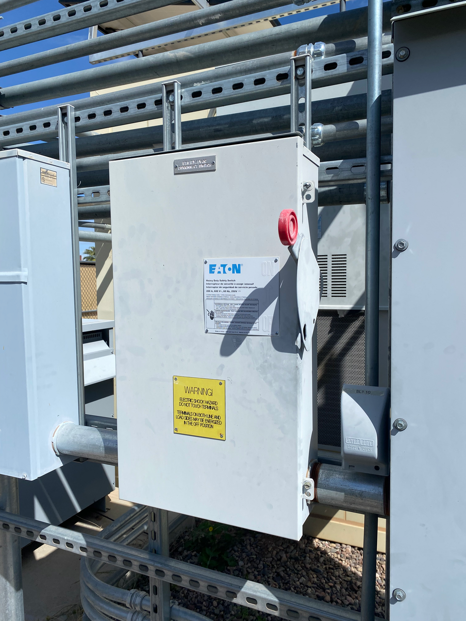
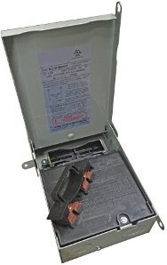
Disconnect switches (Figure 15) should always be placed in the “hot” leg of a circuit and should be the first electrical device in the path from the source. All loads in the circuit can be de-energized by opening the disconnect switch. Only the contacts of the switch will have electrical potential when the switch is open, and the rest of the circuit can then be worked on safely.
Excessive current flowing through a circuit can be dangerous for both people and property. To protect against overheating of circuit components, especially wiring buried in walls and ceilings, something must be placed in the circuit to sense excessive current and open before danger arises. This protection is provided by circuit protectors. There are two main types of circuit protectors: fuses and circuit breakers.
Fuses
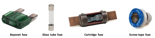
A fuse is used in a circuit to protect against wiring overloads (Figure 16). An overload occurs whenever there is too much current for the size of the wire. This could happen if too many loads are plugged into the same circuit. Because they would be wired in parallel to each other (covered later in this section), the amperage would increase and cause overheating of the conductors.
Another example of an overload would be if a piece of metal fell across the bare wires of a circuit, in effect bypassing the load. This is known as a short circuit or simply short (Figure 17). This means that current has an unrestricted path from the source out and back, without encountering a load. If there is no load in the circuit, there is nothing to limit the amount of current that is being pushed by the source voltage and, consequently the amperage will shoot up to an unsafe point, where it will cause overheating of conductors and possibly a fire.
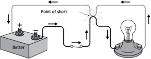
A short could also occur if there is a malfunction in the load, such as the windings in a motor coming in contact with its ground connection. In these cases, the current will always take the path of least resistance, and electrons will surge through the short circuit back to the source. Since the wires in the circuit are sized for the normal operating amperage of the circuit, they are much too small to handle the high amperage cause by the short, so something must be installed in the circuit that will open it whenever current flow gets to an unsafe level.
Time-Delay Fuses
Time-delay fuses are designed and built to withstand the initial current load caused by the starting of electric motors. A motor will take several seconds to come up to speed after starting. This start takes more current than when the motor is up to its operating speed. If a fuse were sized for start-up, it would be too large to protect the wire in the circuit under normal operation, and if it were sized for normal operating amperage, it would blow each time the motor started.
A time-delay fuse has a metal fuse strip that has one end attached to the case of the fuse and the other end attached to a pin held under spring tension (Figure 18). The end of the pin is embedded in solder. If the solder gets hot enough to melt, the pin pulls out of the solder, breaking the circuit.
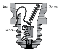
This solder will withstand a momentary overload (such as at motor start-up) without melting. If the heat from the overload is continuous, the solder melts and the circuit breaks. This might take several seconds. If a direct short should occur, the metal fuse strip melts instantly and opens the circuit.
Circuit Breakers
The other type of circuit protector is the circuit breaker (Figure 19). The advantage of circuit breakers over fuses is that the breakers can be reset whereas a fuse must be replaced.
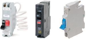
Some circuit breakers look very much like a switch. They usually have a lever with “on” and “off” positions. When the switch is in the “on” position, current flows through a thermal device within the breaker. If excessive current flows through this device, which is simply a bimetal element that will warp when it gets hot, it “trips” the breaker and opens the circuit. When the breaker is tripped, the lever moves into a position that is indicated as neither “on” nor “off” to the observer, but the circuit is open. After the thermal element has cooled sufficiently, the breaker can be manually reset by cycling the lever to the “off” position and then “on.” If the condition that caused the breaker to trip is still there, the breaker won’t allow itself to stay in the “on” position.
Another type of circuit breaker looks like a regular strip fuse with a button protruding from the top. When this breaker trips, it can be manually reset by pushing the button.
Whenever a fuse blows or a breaker trips, the cause should be determined and corrected before replacing or resetting. In a 120 V household circuit, the fuses or circuit breakers are always placed in the energized portion of the circuit. In a 240 V circuit, both energized portions are fused.
Circuits
Before looking at the different ways electrical components can be connected, it is important to understand that a circuit is simply a complete path that allows current to flow. Circuits can be arranged in different ways depending on how we want the loads to behave. The two most common types are:
- Series circuits (one path)
- Parallel circuits (multiple paths)
Each type has different characteristics and uses.
Series Circuits
A series circuit is one in which electrons have only one path they may follow. Loads and switches are wired together end-to-end so that the electricity must pass through the first load to get to the second one, in much the same way as in a series loop hot water heating system (Figure 20). If three light bulbs with equal resistance are wired in series, electricity passing through one of the light bulbs must also pass through the other two in order for the bulb to light up. If one of the bulbs is removed, the path or circuit is broken and none of the bulbs will light. Old-fashioned Christmas lights were wired in series, and if one bulb went out, they all went out. Each bulb had to be tested one at a time until the bad bulb was found. A break in any part of a series circuit ends the flow of electricity throughout the circuit.
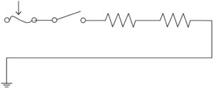
For Ohm’s law calculations, the one constant is that the total resistance in a series circuit will be the sum of all individual resistances in the circuit. For example, if two 20 ohm loads are wired in series, the total resistance of the circuit is 40 ohms (Figure 21).
Watch the following video by Tradestutor (2020) on YouTube titled “Series circuit Explanation (quick and easy)” [4:25].
If you are using a printed copy, you can scan the QR code with your digital device to go directly to the video: Series circuit Explanation (quick and easy)

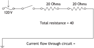
The amperage or current flow everywhere in a series circuit is equal. If an ammeter (an instrument that measures amperage) is placed at any point in the circuit, the amperage will be the same.
Amperage is determined by the total resistance in the circuit. If at any time the resistance in the circuit is changed, the rate of electron flow will be altered. If the total resistance goes up, then the amperage will decrease. If the total resistance drops, the amperage will increase.
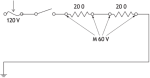
The total resistance in a series circuit can be determined by using a voltmeter (an instrument that measures voltage difference between two points) to measure the voltage drop across each load. Voltage drop is the amount of voltage used at each load. The total circuit voltage will be the sum of the individual voltage drops. For example, the voltage drop across the two loads in the circuit shown in Figure 22 will be 60 volts each. This phenomenon is known as Kirchhoff’s law and is seen in all series circuits. Not all circuits have loads of equal resistance, but Kirchhoff’s law still applies: the sum of the voltage drop across each individual load will equal the supply voltage.
A series circuit will exhibit the following characteristics:
- The total resistance of the circuit is equal to the sum of the resistances of the individual loads of the circuit.
- The amperage or current is the same through all parts of the circuit.
- Kirchhoff’s law states the total voltage applied to the circuit is equal to the sum of the voltage across the individual loads. The voltage drops that occur in a series circuit are proportional to the resistances of the various loads. The load with the greatest resistance will have the largest voltage drop. The load with the least resistance will have the smallest voltage drop. If all loads have the same resistance, then the source voltage divides evenly among the loads.
Parallel Circuits
A parallel circuit is one in which electricity has two or more paths to follow. If three light bulbs are wired in parallel, electricity can pass through any one of the bulbs without passing through the other two (Figure 23). If one of the bulbs is removed, electricity still reaches the other two and they remain lighted.
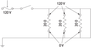
In Figure 23, the voltage potential between the 120 V, also known as the hot (H) terminal, and the 0 V grounded or neutral terminal (N) is 120 V. Since loads A, B and C are wired across H and N, the voltage across each load is also 120 V. In a parallel circuit, the voltage is equal in each path. If loads A, B and C are equal in resistance and also have the same voltage across each, the current (amperage) passing through each of the loads is equal. The total amperage of a parallel circuit can be determined by adding the amperage of all the loads in that circuit.
Watch the following video by Tradestutor (2020) on YouTube titled “Parallel circuit calculations (quick and easy)” [4:46].
If you are using a printed copy, you can scan the QR code with your digital device to go directly to the video: Parallel circuit calculations (quick and easy)

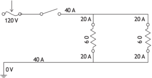
In Figure 24, the total amperage of the circuit is found by adding the amperage draw of load A (20 amps) and the amperage draw of load B (20 amps) to equal a total circuit amperage of 40 amps [latex](20 \text{ A} + 20 \text{ A} = 40 \text{ A})[/latex]. This can be proven by measuring the amperage at H or N with an ammeter and comparing to the sum of the two individual amperage draws.
In Figure 25, if the resistance of load A is 60 ohms and the resistance of load B is 10 ohms, then load A has six times the resistance to current flow as load B does. Since load A has more resistance to current flow than load B, more amperes will flow through load B (remember, the voltage is the same across both loads). In fact, six times as many amps will flow across load B than load A.
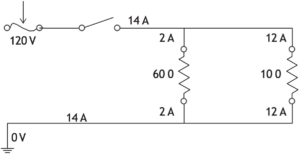
For example, the 60 Ω resistor (load A) draws 2 amperes [latex](\frac{120\text{ V}}{60 \space \Omega} = 2 \text{ A})[/latex] and the 10 Ω resistor (load B) draws 12 amperes [latex](\frac{120\text{ V}}{10 \space \Omega} = 12 \text{ A})[/latex]. To arrive at total amperage for the entire circuit, add A’s amperage (2 A) and B’s amperage (12 A) for a total amperage of 14 amps.
The total resistance in a parallel circuit is not as it is in a series circuit. The total resistance of a parallel circuit is always less than the resistance of the smallest of the individual resistances. For example, if two 20-ohm loads are wired in parallel in a 120 V circuit, as shown in Figure 26, the total amperage of the circuit is 12 A. The total resistance, therefore, can be calculated as [latex]\frac{120\text{ V}}{12 \text{ A}} = 10 \space \Omega[/latex], which is smaller than the smallest individual resistance of 20 Ω.
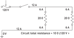
The important thing to remember is that total resistance decreases as more loads are added to a parallel circuit. If too many loads are plugged into an electrical circuit, resistance will decrease and amperage will increase, eventually causing the fuse or circuit breaker to open the circuit.
A parallel circuit will always exhibit these three characteristics:
- The voltage across each path in the circuit is the same as that of the source.
- The total amperage flowing into the circuit is equal to the sum of the amperes flowing through the separate paths. The amperage in the separate paths is inversely proportional to the amount of resistance of the loads in these paths. The path with the greatest resistance will have the least amperage. The path with the smallest resistance will have the most amperage.
- The total resistance of the circuit is always less than the resistance of the smallest of the individual resistances. Total resistance decreases as more loads are added to the parallel circuit.
Series-Parallel Circuits
Series-parallel circuits are merely combinations of series and parallel circuits. Figure 27 is an example of a series-parallel circuit. Loads A, B, C and D are all in the circuit. When working with series-parallel circuits, divide the overall circuit into sub-circuits. This will result in several series and/or parallel sub-circuits that can then be analyzed by using the fundamentals of series and parallel circuits discussed earlier.
For instance, loads B (5 Ω) and C (10 Ω) in Figure 27 comprise a parallel sub-circuit. That parallel sub-circuit is in series with loads A and D. The characteristics of parallel circuits can be used to analyze sub-circuits B and C. Then, by considering sub-circuit B/C as a single load in series with A and D, the characteristics of series circuits can be used to analyze the larger parent circuit.
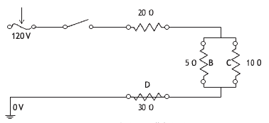
The resistance of two loads in parallel can be calculated using the following formula:
[latex]\quad\text{R} = \frac{\text{R}_1 \times \text{R}_2}{\text{R}_1 + \text{R}_2}[/latex]
For sub-circuit B/C, the resistance would be:
[latex]\quad\text{R} = \frac{5 \times 10}{5 + 10}\\ \quad= \frac{50}{15}\\ \quad= 3.33[/latex]
When the resistance of B/C (3.33 Ω) is added to the two other resistances of 20 Ω and 30 Ω, the total resistance of the circuit can be calculated to be 53.33 Ω. The amperage flowing through the circuit can then be calculated by dividing the total resistance into the source voltage, to get 2.25 amps [latex](\frac{120\text{ V}}{53.33 \space \Omega} = 2.25 \text{ A})[/latex].
Any electrical circuit can be reduced to (1) a source, (2) a path, conductors, and (3) a single resistance, a load.
Transformers
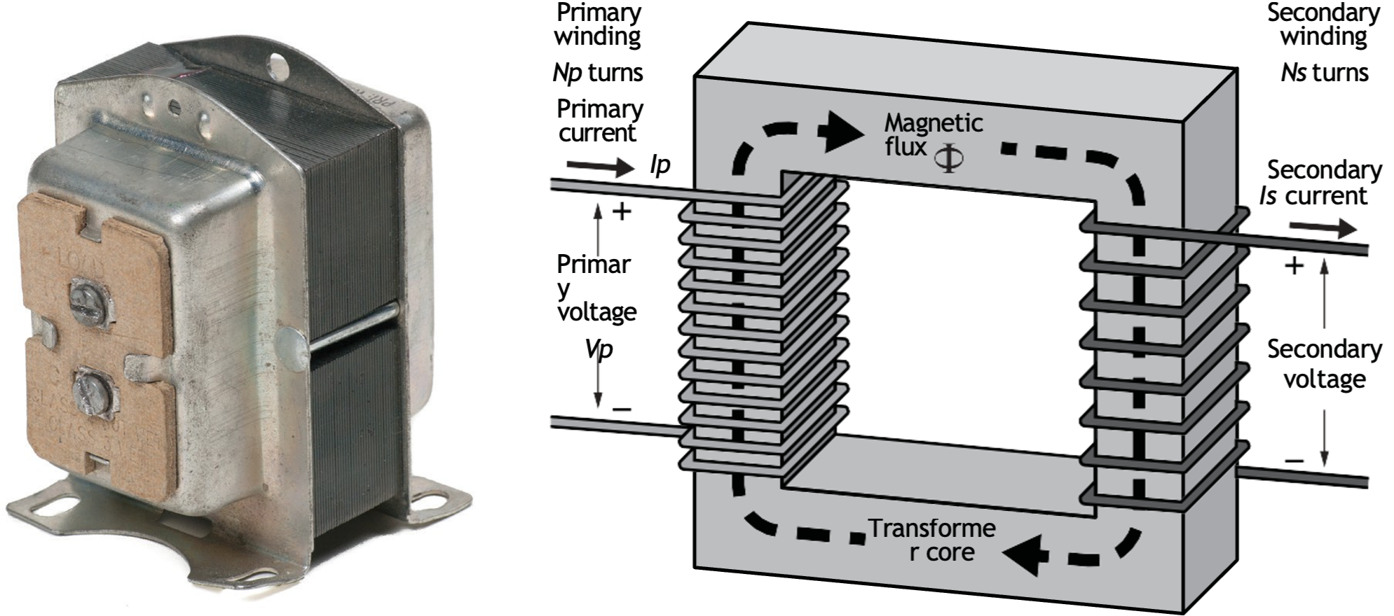
A transformer is an electrical device used to change alternating current (AC) voltage to either a higher or lower level. Transformers only work with AC because they rely on a changing magnetic field. If a transformer changes 120 VAC to 24 VAC, it is called a step-down transformer (Figure 28). If it increases voltage (for example, from 120 VAC to 12,000 VAC), it is called a step-up transformer. An isolation transformer does not change voltage but provides protection from electrical shock by separating circuits. An isolation transformer neither steps up or down but, rather, provides galvanic protection from electric shock to sensitive equipment. Transformers are available in a variety of capacities for isolation, stepping up or stepping down AC voltages. A transformer is considered to be a load on the primary side and a source on the secondary side.
Construction and Operation
The construction of a transformer is relatively simple. It consists of two coils of wire, called windings. Windings or wire are placed around one side of an iron ring:
- The primary winding is connected to the power source.
- The secondary winding delivers the output voltage.
There is no direct electrical connection between the primary and secondary windings. Instead, energy is transferred through magnetic induction.
Two important principles explain how transformers work:
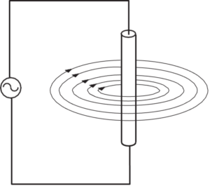
- When electric current flows through a conductor, it creates a magnetic field (Figure 29).
- When a conductor moves through a magnetic field, a voltage is induced in that conductor (Figure 30).
In an AC circuit, current is constantly changing direction. This causes the magnetic field around the primary winding to continually grow and collapse. This changing magnetic field induces a voltage in the secondary winding.
Because direct current (DC) flows in only one direction and does not continuously change, DC cannot be used to operate a transformer.
Voltage Transformation
The output voltage of a transformer depends on the ratio of turns (loops of wire) in the windings:
- If the secondary winding has more turns than the primary, the voltage increases.
- If the secondary winding has fewer turns, the voltage decreases.
Power Rating (VA)
Transformers are rated based on the amount of power they can handle. This is expressed in volt-amperes (VA).
For example:
[latex]\quad 24 \text{ V} \times 2 \text{ A} = 48 \text{ VA}[/latex]
The unit VA is equivalent to watts, since power is calculated as voltage multiplied by current.
When replacing a transformer, if one with an identical wattage cannot be obtained, use one with a higher VA rating. If one of a lower rating is used and the original had been sized close to its capacity, the new transformer will burn out in time due to excessive heat created by an undersized secondary winding.
Sensitive Ammeter
A magnetic field must remain in motion if a continuous voltage is to be induced in the secondary windings. The magnetic lines of force must continually cut the conductor. In AC current, electrons flow in one direction, then stop and flow in the opposite direction. This occurs 60 times a second. This means that as electrons flow in the primary winding, the magnetic field builds up in intensity. When electron flow stops, the magnetic field collapses. As the electron flow changes direction, the magnetic field again builds up, this time in the opposite direction. It is this pulsating magnetic field moving in and out of the secondary windings that induces voltage. Because a DC source produces current flowing in one direction at a constant level, it cannot be used with a transformer.
The AC voltage output of the secondary winding of the transformer is determined by the ratio of the number of windings in the secondary to the number of windings in the primary. If the number of windings in the secondary is greater than in the primary, more electrons are excited and the voltage produced will be higher than in the primary. If there are fewer windings in the secondary than in the primary, fewer electrons are excited and a lower voltage is produced.
Solenoids
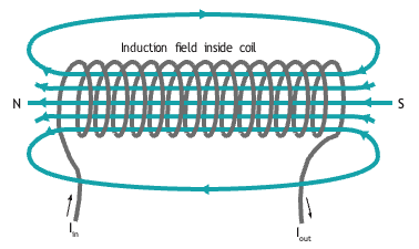
A solenoid consists of a coil of insulated conductor wire and a movable iron rod (Figure 31).
A solenoid may also be called an electromagnet. The tip of the iron rod is positioned just inside the entrance of the coil opening. When the coil is electrically energized and current flows through it, the resulting intensified magnetic field of the coil pulls the iron rod into the centre of the coil. The iron rod will remain in this position until the coil is de-energized. Normally, gravity allows the iron core to return to its original position, although some solenoids, particularly those used in pressurized water systems, use a spring on the return. Solenoids are used for such things as valves, doorbells, locking devices and many other types of electromechanical equipment.
Relays
Electrical relays use the principle of the electromagnet. A relay consists of a coil of insulated wire with an iron core fixed within it (Figure 32). A movable metal armature is located nearby the end of the iron core. The armature has an electrical contact on one end. Another contact is stationary. When the relay becomes electrically energized, the iron core becomes magnetized and attracts the metal armature toward it. When the armature moves to the magnet, the armature contact closes against the stationary contact. When the relay is de-energized, the core is de-magnetized. A spring returns the armature to its original position and the contacts separate.
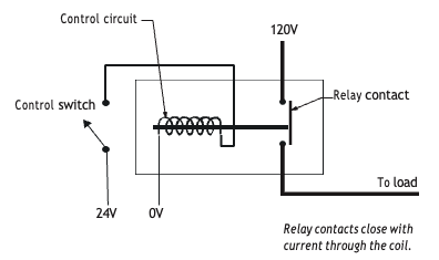
A relay is used when it is necessary to control an electrical device that operates on, for instance, 120 VAC by using a control voltage of another value, for instance, 24 VAC. If the 24 V were to be directly interconnected with the 120 V, the 24 V components would likely burn out. This strategy is used quite successfully in hydronic heating and air conditioning, where 120 V or 240 V motors are switched on and off by a 24 V control circuit. The relay would be identified as a load on the 24 V side and a switch on the 120 or 240 V side.
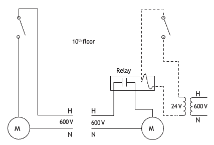
Another reason to use a relay might be to operate a piece of large equipment from a remote location. For instance, a large electric motor operating on 600 VAC and drawing many amps needs to be controlled from a location that is 10 storeys above it (Figure 33). To do this, heavy wires would have to be routed from the source in the basement up to the 10th floor, through a heavy switch, then back down to the motor and subsequently back to the power panel. If a relay were used, a 24 VAC source (step-down transformer) located in the basement close to the motor could supply a light wire with voltage right up to the 10th floor, through a light-duty switch, back down to the coil in the relay. The normally open relay contacts would have the 600 V wired through it to the motor. When the switch on the 10th floor is closed, 24 V is sent to the relay coil, which pulls in the armature and closes the normally open contacts, sending the 600 V to the motor. The addition of an inexpensive relay is more than offset by the cost savings realized by not having to run very much heavy, expensive wire.
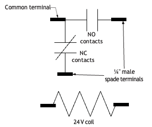
There are several types of relays. The relay described in the previous examples is used to close or complete a circuit. This type of relay contains a set of normally open (NO) contacts. This means that the contacts are open when the relay is not energized and closed when the relay is energized. Another type of relay is used to open a circuit. This relay contains a set of normally closed (NC) contacts. This means that the contacts are closed when the relay is not energized and opened when the relay is energized.
Some relays are also capable of opening or closing several circuits at the same time.
The description of this switching action is the same for relays as it is for manual switches. Figure 34 shows a typical relay capable of opening and closing several circuits.
Capacitors
A capacitor is an electrical component composed of two metal plates separated by an insulator that stores a charge to help equipment such as motors and compressors run more efficiently.
When a capacitive motor starts up, there is a large current draw on the system that is bolstered by the stored charge captured in the capacitor, supporting smooth motor start and run.
Capacitance, measured in the SI system in farads (F), describes how efficiently a capacitor stores a charge.
Ampacity
Ampacity is an electrical rating used to properly size conductors used for electrical wiring circuits. This rating is based on a few variables such as type of conductor, size of conductor and insulation that covers the conductor. Manufacturers put ampacity ratings on the nameplates of their electrical equipment. When selecting wire size for equipment, take the ampacity rating shown on the equipment and apply this to the ampacity tables found in the Canadian Electrical Code. Normally, conductors that supply electricity to any equipment that has a motor have to be rated at 125% of the equipment’s rated ampacity. For example, if a motor’s rated current draw is 5 amps, the conductors will have to be capable of 125% of 5 amps, or 6.25 amps. The extra 25% is to make sure that the wiring will not catch fire in the event of an electrical overload. If the circuit is properly fused, an overload will blow the fuse or trip the breaker before the wire gets hot enough to ignite its coating of insulation.
Supplementary Videos
To better understand motors and electrical principles, check out the excellent information in some of “The Engineering Mindset” videos:
- Alternating Current Basics: How does an Electric Motor work? (DC Motor) [4:49]
- AC and DC Electricity: AC and DC Electricity basics [2:56]
- How DC Motors Work: How does an Electric Motor work? (DC Motor) [4:49]
- Induction Motors: Induction Motor Basics [8:38]
- How 3-phase Electricity Works: How Three Phase Electricity works – The basics explained [7:52] (originally linked: AC and DC Electricity basics [2:56])
- Main electrical panel explained: Main electrical panel explained – Load center – service panel [10:18]

Self-Test C-2.2: Electrical Circuits
Complete Self-Test C-2.2 and check your answers.
If you are using a printed copy, please find Self-Test C-2.2 and Answer Key at the end of this section. If you prefer, you can scan the QR code with your digital device to go directly to the interactive Self-Test.
References
BCcampus. (n.d.). Playlist: Tools and equipment videos. BCcampus MediaSpace. https://media.bccampus.ca/playlist/details/0_3g8xp22x/categoryId/175673 Playlist Details – Trades Access Common Core Line C: Tools and Equipment Videos – BCcampus
BC Industry Training Authority. (2019). Piping trades apprenticeship program: Use Tools and Equipment—Level 1 harmonized [Binder]. Crown Publications, Queen’s Printer for British Columbia. https://www.crownpub.bc.ca/Product/Details/7960000261_S
- Plumber: Competency O-1 Use the Principles of Electricity
- Steamfitter: Level 2 Competency K-1 Use the Principles of Electricity
- Sprinkler Fitter: Competency C-1 Use Mathematics and Science
Camosun College. (2019). Line D: Tools and Equipment—Competency D-2: Apply Science Concepts to Trades Applications (Rev. ed.) [Learning guide]. BCcampus. https://collection.bccampus.ca/textbook/qFKGAJ78/
Camosun College. (2015). Trades Access Common Core Competency D-2: Apply Science Concepts to Trades Applications. Victoria, B.C.: Crown Publications. Download for free from the B.C. Open Textbook Collection (https://open.bccampus.ca/browse-ourcollection/find-open-textbooks/).
Camosun College. (2015). Line E – Electrical fundamentals competency E-1: Describe the Basic Principles of Electricity. BCcampus.
https://collection.bccampus.ca/textbook/Nf7jVbAg/
Camosun College. (2015). Line E – Electrical fundamentals competency E-2: Identify common circuit components and their symbols. BCcampus.
https://collection.bccampus.ca/textbook/fGcTBtJh/
CSA Group. (2024). CSA C22.1:24: Canadian electrical code, Part I (26th ed.): Safety standard for electrical installations. CSA Group Store. https://www.csagroup.org/store/product/CSA_C22.1:24/
Science ABC. (2024, July 22). Electromagnetism explained in simple words [Video]. YouTube. https://www.youtube.com/watch?v=nllCgjlWAF4
SkilledTradesBC. (2025). House panel (Figure 11 [modified]) [Image]. In Plumbing level 4 (Describe electric motors). BCcampus. https://opentextbc.ca/plumbing4e/chapter/describe-electric-motors/
The Engineering Mindset. (2022, November 8). AC and DC electricity basics [Video]. YouTube. https://www.youtube.com/watch?v=2jqJZxxX6gQ&list=RDCMUCk0fGHsCEzGig-rSzkfCjMw&index=8
The Engineering Mindset. (2022, November 8). Alternating current basics [Video]. YouTube. https://www.youtube.com/watch?v=1AaUK6pT_cE&list=RDCMUCk0fGHsCEzGig-rSzkfCjMw&index=7
The Engineering Mindset. (2022, November 8). How does an electric motor work? (DC motor) [Video]. YouTube. https://www.youtube.com/watch?v=1AaUK6pT_cE&list=RDCMUCk0fGHsCEzGig-rSzkfCjMw&index=7
The Engineering Mindset. (2022, November 8). How three-phase electricity works – The basics explained [Video]. YouTube. https://www.youtube.com/watch?v=4oRT7PoXSS0
The Engineering Mindset. (2022, November 8). Induction motor basics [Video]. YouTube. https://www.youtube.com/watch?v=AOC7uTnxmTI
The Engineering Mindset. (2022, November 8). Main electrical panel explained – Load center – service panel [Video]. YouTube. https://www.youtube.com/watch?v=UBERduCp3Wo
Tradestutor. (2020, January 12). Ohms law quick and easy [Video]. YouTube. https://www.youtube.com/watch?v=MPtduUm3piU
Tradestutor. (2020). Parallel circuit calculations (quick and easy) [Video]. YouTube. https://www.youtube.com/watch?v=8ECyb8sf_mk
Tradestutor. (2020). Series circuit explanation (quick and easy) [Video]. YouTube. https://www.youtube.com/watch?v=WWEC_6f8PFA
Media Attributions
All figures are sourced from Industry Training Authority (2019) and/or Camosun College (2019) and are used under the Creative Commons Attribution 4.0 (CC BY 4.0) licence unless otherwise noted. Images copyrighted by the BC Industry Training Authority are licensed under a Creative Commons Attribution-NonCommercial-ShareAlike 4.0 (CC BY-NC-SA 4.0) licence.
- Figure 3 Toaster, by Nick Carson on en.wikipedia is used under the CC BY 3.0 license.
- Figure 14 Utility Disconnect Switch by Rsparks3 on Wikimedia Commons is used under the CC0 1.0 public domain license.
A complete path that allows electricity to flow from a power source, through wires and devices, and back to the source. (Section C-2.2)
The pressure that pushes electricity through a circuit. (Section C-2.1)
The flow of electricity (electrons) through a wire or circuit. (Section C-2.2)
A measure of how much a material slows down electric flow. (Section C-2.1)
A complete path that electricity can travel through, usually made of wires and components like batteries and devices. (Section C-2.1)
A unit used to measure electric charge. (Section C-2.1)
A unit used to measure voltage, which is the push that moves electricity through a circuit. (Section C-2.1)
A material that allows electric current to flow easily because it has low electrical resistance. Conductors have free electrons that move readily when a voltage is applied.
Common examples include copper, aluminum, gold, and most metals. (Section C-2.1)
A unit used to measure how much electric current is flowing in a circuit. (Section C-2.2)
A device in a circuit that uses electricity to do work (like a light bulb or motor). (Section C-2.2)
A unit used to measure resistance in a circuit. (Section C-2.2)
A type of resistance in AC circuits that slows down the flow of electricity. (Section C-2.2)
A rule that explains how electricity moves in a circuit. It says that the amount of electrical push (voltage) equals the flow of electricity (current) multiplied by how much the material resists it (resistance). (Section C-1.1)
The energy an object has because it is moving. The faster it moves, the more kinetic energy it has. (Section C-1.15)
The rate at which electrical energy is used to do work.
(Section C-2.2)
A unit used to measure electrical power. (Section C-2.2)
“Pounds per square inch.” It is a unit used to measure pressure, or how much force is pushing on a surface. For example, it can be used to measure the air pressure in a tire. (Section C-1.2)
Electric current that flows in one direction only, like the electricity from a battery. (Section C-2.1)
Electric current that changes direction back and forth many times per second. (Section C-2.1)
The process of producing electricity in a conductor by placing it in a changing magnetic field, without direct contact. (Section C-2.2)
Produced or generated by a magnetic field, without direct electrical contact. (Section C-2.2)
The process of creating electricity when a magnet moves near a wire or a wire moves in a magnetic field. (Section C-2.1)
A type of electrical power supply that uses one alternating current (AC) voltage, commonly used in homes and small buildings. (Section C-2.2)
A type of electrical power supply that uses three alternating currents, providing more consistent and efficient power for large equipment and industrial use. (Section C-2.2)
A device that increases or decreases AC voltage. (Section C-2.2)
A basic electrical circuit that includes a power source, conductors, a control device (like a switch), and a load, forming a complete path for electricity to flow. (Section C-2.2)
A device that opens or closes a circuit to control the flow of electricity. (Section C-2.2)
A circuit in which the path is broken, so electricity cannot flow. (Section C-2.2)
A circuit in which the path is complete, allowing electricity to flow. (Section C-2.2)
The distance from the centre of a fitting to its face. It is the same as centre-to-face and is equal to the fitting allowance (FA) plus the thread engagement (TE). (Section C-1.7)
The part of a switch that carries current and opens or closes a circuit. (Section C-2.2)
Metal strips or bars inside an electrical panel that distribute electricity to multiple circuits. (Section C-2.2)
When two electrical voltages reach their peaks at different times, rather than at the same time. (Section C-2.2)
A switch that is turned in a circle to connect to one of several positions or circuits. (Section C-2.2)
A safety switch used to completely shut off power to a circuit or equipment so it can be worked on safely. (Section C-2.2)
A safety device that melts and breaks the circuit if too much current flows. (Section C-2.2)
An unintended path that allows electricity to flow too easily, often causing danger. (Section C-2.2)
A fuse designed to allow a short burst of higher current (such as when a motor starts) without blowing, but will open the circuit if the overload continues for too long. (Section C-2.2)
A reusable safety device that automatically opens (shuts off) a circuit when too much current flows, preventing overheating and damage. (Section C-2.2)
When a circuit breaker automatically shuts off electrical flow because too much current or a fault is detected, protecting the circuit from damage. (Section C-2.2)
A circuit with more than one path for electricity to flow. (Section C-2.2)
A circuit with only one path for electricity to follow. (Section C-2.2)
A measuring device used to check the voltage (electrical pressure) between two points in a circuit. (Section C-2.2)
The reduction in voltage as electricity flows through a circuit, caused by resistance in wires or components. (Section C-2.2)
A rule stating that the total voltage in a circuit is equal to the sum of the voltage drops across all components in that circuit. (Section C-2.2)
An electrical circuit that combines both series and parallel connections, with some components in a single path and others in multiple paths. (Section C-2.2)
A transformer that reduces voltage from a higher level to a lower level. (Section C-2.2)
A transformer that increases voltage from a lower level to a higher level. (Section C-2.2)
A transformer that transfers electrical energy between circuits while keeping them electrically separate, helping protect people and equipment from electric shock. (Section C-2.2)
Coils of wire in a device (such as a transformer) that carry current and create or receive a magnetic field. (Section C-2.2)
The coil of wire in a transformer that is connected to the power source and receives electrical energy. (Section C-2.2)
The coil of wire in a transformer that delivers the output voltage after energy is transferred. (Section C-2.2)
The process of generating electricity in a conductor when it is exposed to a changing magnetic field. (Section C-2.2)
A coil of wire that becomes a magnet when electricity flows through it, often used to move a metal rod or control a device. (Section C-2.2)
A magnet made by electricity that can be turned on and off. (Section C-2.1)
Electrical devices that use a small current to control a larger current by opening or closing a switch. (Section C-2.2)
An electrical component that stores and releases electrical energy, helping devices like motors start and run smoothly. (Section C-2.2)
The ability of a capacitor to store electrical energy; measured in farads (F) in the SI system. (Section C-2.2)
The unit used to measure capacitance; it shows how much electrical energy a capacitor can store. (Section C-2.2)
The maximum amount of electrical current a wire can safely carry without overheating. (Section C-2.2)