C-1.14 Define Mechanical Advantages as it Relates to Fluid Power
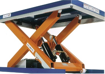
Remember that Pascal's law states that when there is an increase in pressure at any point in a confined fluid, there is an equal increase at every other point in the container.
He is also credited with demonstrating and clearly defining the principles involved in the hydraulic press: the multiplication of force and and the relationship between piston movement and force.
Most machines that move very large, very heavy objects use a hydraulic system that applies force to levers, gears, or pulleys. A hydraulic system uses a liquid under pressure to move loads. It is able to increase the mechanical advantage (MA) of the levers in the machine.
Modern construction projects use hydraulic equipment because the work can be done more quickly and safely. There are many practical applications of hydraulic systems that perform tasks, making work much easier.
The hydraulic lift is one of many mechanical systems that use Pascal’s law. A hydraulic lift is a mechanical system that raises heavy objects, such as a vehicle on a service station lift. A hydraulic lift uses a fluid under pressure in a closed system.
A hydraulic lift consists of a small cylinder and a large cylinder connected together by a pipe (Figure 2). Each cylinder is filled with a hydraulic fluid, usually oil. Water is not used in a hydraulic lift for two reasons: it is not a good lubricant, and it can cause parts of a system to rust.
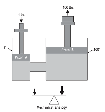
Note that each cylinder also has a type of platform, or piston, that rests on the surface of the oil.
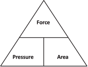
Using the relationship triangle shown in Figure 3, we can see that the force exerted by the large piston is the area of the piston multiplied by the pressure of the hydraulic fluid.
Suppose you apply 500 N of force to the small piston with an area of 5 cm2. The pressure on the small piston is expressed in the following equation:
[latex]\quad\text{P} = \frac{\text{F}}{\text{A}}\\ \quad\text{P} = \frac{500\text{ N}}{5\text{ cm}^2}\\ \quad\text{P} = 100\frac{\text{N}}{\text{ cm}^2}[/latex]
Pascal’s law states that this pressure is transmitted unchanged throughout the liquid. Therefore, the large piston will also have the same pressure applied to it: [latex]100 \frac{\text{N}}{\text{ cm}^2}[/latex]. However, the total area of the large piston is greater than the area of the small piston. The large piston’s area is 50 cm2.
This means the force on the large piston is greater.
[latex]\quad100\frac{\text{N}}{\text{ cm}^2} \times 50\text{ cm}^2 = 5,000\text{ N}[/latex]
This is 10 times the force applied to the small piston.
Previously in this C-1 section, we stated that the pascal (Pa) is the standard unit of pressure. One pascal of pressure is a force of 1 newton per square metre. This is a small pressure unit, so most pressures are given in kilopascals (kPa).
[latex]\begin{aligned} \frac{1\text{N}}{\text{ cm}^2} &= 1\, \text{ Pa} = 0{.}001\text{ kPa} \end{aligned}[/latex]
Because a small effort force produces a large force on a load, a hydraulic lift provides a mechanical advantage.
Pascal’s Law and Mechanical Advantage
In Figure 4 the diameter of the small piston of the hydraulic lift is 1 in.
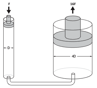
Mechanical advantage is directly related to area, not diameter, so the area of the piston’s face must be calculated:
[latex]\quad\text{A} = \text{D}^2 \times 0.7854\\ \quad\text{A} = 1^2 \times 0.7854\\ \quad\text{A} = 0.7854 \text{ in.}^2[/latex]
If you push down on the piston with a force of 10 lb, you will generate a pressure in the fluid of 12.73 psi:
[latex]\quad\text{P} = \frac{\text{F}}{\text{A}}\\ \quad\text{P} = \frac{10\text{ lb}}{0.7854\text{ in.}^2}\\ \quad\text{P} = 12.73\frac{\text{lb}}{\text{ in.}^2}[/latex]
Now examine the area of the large piston. The diameter is 4 in. This would have a corresponding area of:
[latex]\text{A} = \text{D}^2 \times 0.7854\\ \text{A} = 4^2 \times 0.7854\\ \text{A} = 12.566 \text{ in.}^2[/latex]
This is an increase in area of 16 times the small piston area. According to Pascal’s law, the pressure on every unit of area on that piston will be [latex]12.73\frac{\text{lb}}{\text{in.}^2}[/latex]. Since there are 12.566 in.2 of area, the total force on the large piston will be:
[latex]\quad\text{F} = \text{P} \times \text{A}\\ \quad\text{F} = 12.73\frac{\text{lb}}{\text{ in.}^2} \times 12.566\text{ in.}^2\\ \quad\text{F} = 159.97\text{ lb}[/latex]
This hydraulic lift has a mechanical advantage of 16. Unfortunately, mechanical advantage in hydraulic systems has a trade-off. That trade-off is the increased distance the smaller force must move to make the larger force move a smaller distance. Because of this reality, you would have to push the piston 16 times farther than the distance you could lift the load. In other words, you must push the piston farther to lift the load a shorter distance.
Calculating Mechanical Advantage (MA)
A machine makes work easier for you by increasing the amount of force that you exert on an object. This produces a mechanical advantage (MA), which is the amount of force that is multiplied by the machine. The force applied to the machine (by you) is the input force. The force that is applied to the object (by the machine) is the output force.
The mechanical advantage of a machine is the output force divided by the input force.
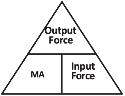
The mechanical advantage is the force ratio of a machine. The more a machine multiplies the force, the greater is the mechanical advantage of the machine.
Example:
According to engineering reports, 110 hydraulic jacks were used to lift the massive Ekofisk offshore complex in the North Sea. An output force of 390,000,000 N was required to raise the complex. What input force would have to be provided to each jack if the overall mechanical advantage of the jacks was 1,500?
Solution:
[latex]\quad\text{Input Force} = \frac{\text{Output Force}}{\text{MA}}\\ \quad\text{Input Force} = \frac{390,000,000 \text{ N}}{1,500}\\ \quad\text{Input Force} = 260,000 \text{ N}\\ \quad\text{Input Force for each jack} = \frac{260,000 \text{ N}}{110 \text{ jacks}}\\ \quad\text{Input Force for each jack} = 2,363.6 \text{ N}[/latex]

Self-Test C-1.14: Define Mechanical Advantages as it Relates to Fluid Power
Complete Self-Test C-1.14 and check your answers.
If you are using a printed copy, please find Self-Test C-1.14 and Answer Key at the end of this section. If you prefer, you can scan the QR code with your digital device to go directly to the interactive Self-Test.
Complete the C-1.4 Self-Test: Hydraulic Jack Calculations Table (Question 8)
Using a separate sheet of paper, calculate the missing values in the table for each scenario. Show all your work and include the correct units for every answer. You may also print the table if that’s easier (see link below). Answer keys for all self-tests are also in the back of this section.
For each row:
- Use the given values to solve for the unknowns.
- Apply the appropriate formulas (e.g., pressure = force ÷ area, area = diameter² × 0.7854, mechanical advantage = output force ÷ input force).
- Ensure your final answers are clearly labeled with units (e.g., lb, N, in², cm², psi, kPa).
Note:
- Some values are provided to help you calculate the remaining values.
- You may need to convert between units (e.g., mm to cm, or in to cm) where appropriate.
- Keep your calculations organized and easy to follow.
Helpful Tip:
Work step-by-step—first calculate area, then pressure, and finally force and mechanical advantage.
Downloadable/printable table: C-1.4_Self-Test_Hydraulic_Jack_Table
|
Small piston force |
Small piston diameter |
Small piston area |
Small piston travel distance |
Fluid pressure |
Large piston diameter |
Large piston area |
Large piston travel distance |
Force exerted by large piston |
Mechanical advantage |
|
25 lb |
2.5 in. |
|
|
|
7.5 in. |
|
7 in. |
|
|
|
44 lb |
3.7 in. |
|
14 in. |
|
|
73 in.2 |
|
|
|
|
78 lb |
5.5 in. |
|
|
|
|
|
12 in. |
|
14 |
|
2,375 N |
8 cm |
|
1.8 m |
|
|
|
|
9,449 N |
|
|
1,850 N |
|
40 cm2 |
|
|
27.64 cm |
|
70 mm |
|
15 |
|
|
|
|
|
|
|
6,120 cm2 |
113 mm |
10,770 N |
34 |
References
BCcampus. (n.d.). Playlist: Tools and equipment videos. BCcampus MediaSpace. https://media.bccampus.ca/playlist/details/0_3g8xp22x/categoryId/175673 Playlist Details – Trades Access Common Core Line C: Tools and Equipment Videos – BCcampus
BC Industry Training Authority. (2019). Piping trades apprenticeship program: Use Tools and Equipment—Level 1 harmonized [Binder]. Crown Publications, Queen’s Printer for British Columbia. https://www.crownpub.bc.ca/Product/Details/7960000261_S
- Plumber: Competency C-1 Use Mathematics and Science
- Steamfitter: Competency C-1 Use Mathematics and Science
- Sprinkler Fitter: Competency C-1 Use Mathematics and Science
Camosun College. (2019). Line C: Tools and Equipment—Competency D-2 Apply Science Concepts to Trades Applications (Rev. ed.) [Learning guide]. BCcampus. https://collection.bccampus.ca/textbook/fkXxtNTn/
Camosun College. (2015). Trades Access Common Core Competency D-2 Apply Science Concepts to Trades Applications. Victoria, B.C.: Crown Publications. Download for free from the B.C. Open Textbook Collection (https://open.bccampus.ca/browse-ourcollection/find-open-textbooks/).
Camosun Innovates. (2022). Tools and Equipment Videos [Video playlist]. Camosun College/BCcampus. https://camosuninnovates.opened.ca/
Flinn, C. (n.d.). OER for Trades: Math for Trades [Video collection]. BCcampus MediaSpace. https://media.bccampus.ca/channel/OER%2Bfor%2BTrades%3A%2BMath%2Bfor%2BTrades/175670
Note: these videos align with the open textbooks Math for Trades: Volume 1 and Math for Trades: Volume 2. All videos are by Chad Flinn and available under a Creative Commons Attribution 4.0 Licence.:
Media Attributions
All figures are sourced from Industry Training Authority (2019) and/or Camosun College (2019) and are used under the Creative Commons Attribution 4.0 (CC BY 4.0) licence unless otherwise noted. Images copyrighted by the BC Industry Training Authority are licensed under a Creative Commons Attribution-NonCommercial-ShareAlike 4.0 (CC BY-NC-SA 4.0) licence.
Using liquids to create and control movement and force. (Section C-1.4)
A rule that says pressure applied to a liquid in a closed space is spread evenly in all directions. (Section C-1.14)
The force pushing on a surface, like how air pushes on the inside of a pipe. (Section C-1.16)
A liquid that is trapped inside a container or system. (Section C-1.4)
A machine that uses liquid pressure to push or press objects with great force. (Section C-1.14)
A moving part inside a cylinder that pushes or is pushed by a liquid or gas. (Section C-1.14)
A system that uses liquid under pressure to move or lift things. (Section C-1.14)
How much a machine increases your force; The mechanical advantage (MA) of a machine is the output force divided by the input force: (Section C-1.14)
A machine that uses liquid pressure to lift heavy objects. (Section C-1.4)
A system where the liquid stays inside and does not leak out. (Section C-1.14)
A liquid (usually oil) used to transfer force in a hydraulic system. (Section C-1.14)
A substance (like oil) that helps parts move smoothly and reduces friction. (Section C-1.14)
The metric unit used to measure pressure. (Section C-1.6)
A unit used to measure pressure; it is larger than a pascal. (Section C-1.14)
The amount of space inside a shape (Section C-1.3)
The distance across a circle through the centre. (Section C-1.3)
The force you put into a machine. (Section C-1.14)
The force that comes out of a machine after it multiplies your input force. (Section C-1.14)
The comparison between the output force and the input force of a machine. It shows how much a machine increases your force. (Section C-1.14)