
C-1.7 Calculate Piping Measurements

Threaded Pipe
When installing threaded fittings in a piping system, you must cut the pipe, thread its ends and screw fittings onto the threaded ends. Because the fittings actually add length to the pipeline, you must take measurements and perform calculations to determine how long to cut the pipe (which will be less than the centre-to-centre [C–C] measurement of the fittings). When pipe trades workers install pipe and fittings, a thorough knowledge of fractions and decimals is essential. In addition, the calculations require you to be familiar with the terminology associated with this piping practice.
Terminology
Fitting allowance (FA): The measured distance from the end of the pipe inside a fitting to the centre of the fitting. This value changes depending on the type and size of the fitting.
Thread engagement (TE): The distance from the face of a fitting to how far the pipe screws into it. This distance changes depending on the size of the pipe.
Take off (TO): The total amount of length removed from a pipe measurement to account for all fittings in a connection. It is usually the sum of two fitting allowances—one at each end of the pipe. When the two fitting allowances are added together, the dimension is called the total take off.
Throw: Also known as centre to face (C-to-F), this is the distance from the centre of a fitting to its face (end opening) and is also equal to the sum of the fitting allowance (FA) and the thread engagement (TE) (Figure 1).
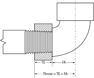
Allowance for Thread Engagement
Whenever a fitting is threaded onto a pipe, a certain allowance must be made in the length of the pipe to account for the thread engagement, or the thread allowance.
Example:
A length of [latex]1\text{"}[/latex] pipe has an elbow at one end and a tee at the other. It is [latex]17\text{"}[/latex] from the centre of the elbow to the centre of the tee. The distance from the centre of the elbow to its face (throw) is [latex]1\frac{1}{2}\text{"}[/latex]. The distance from the centre of the tee to its face (throw) is also [latex]1\frac{1}{2}\text{"}[/latex]. The thread engagement for all [latex]1\text{"}[/latex] threaded fittings is [latex]\frac{11}{16}\text{"}[/latex].
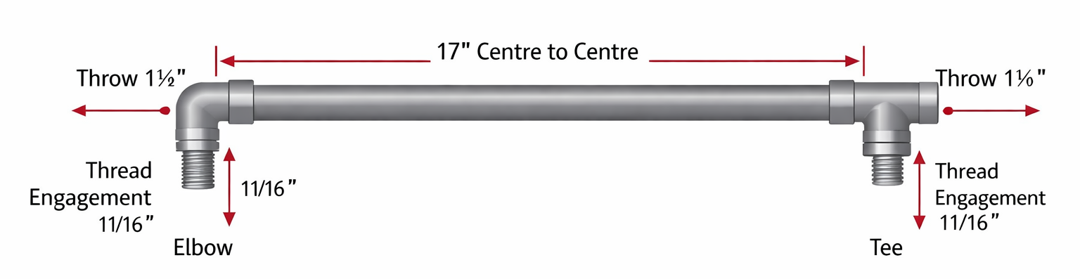
Solution:
The length of the pipe will be [latex]17\text{"}[/latex] minus [latex]1\frac{1}{2}\text{"}[/latex] at each end plus [latex]\frac{11}{16}\text{"}[/latex] at each end, or [latex]15\frac{3}{8}\text{"}[/latex] end to end.
Common mistake: Forgetting to subtract fitting allowances at both ends of a pipe. Always account for fittings on both sides when calculating cut length.
Measuring Threaded Pipe
There are seven general methods of measuring threaded pipe in piping installations (Figure 3):
- End–to–end (E–E): The measurement from one end of a piece of pipe to the other end.
- End–to–centre (E–C): The measurement from one end of the pipe to the centre of the fitting on the other end of the pipe.
- End–to–back (E-B): The measurement one end of the pipe to the back of the fitting on the other end of the pipe.
- Centre–to–centre (C–C): The measurement from the centre of the fitting on one end of a piece of pipe to the centre of the fitting at the other end.
- Face–to–face (F–F): The measurement from the face of the fitting on one end of a piece of pipe to the face of the fitting at the other end.
- Centre–to–back (C–B): The measurement from the centre of the fitting on one end of the pipe to the back of the fitting on the other end of the pipe.
- Back–to–back (B–B): The measurement from the back of the fitting on one end of a piece of pipe to the back of the fitting at the other end.
- Overall centre–to–centre: The total distance from the centre of the first fitting to the centre of the last fitting in a pipe assembly, including all fittings in between.
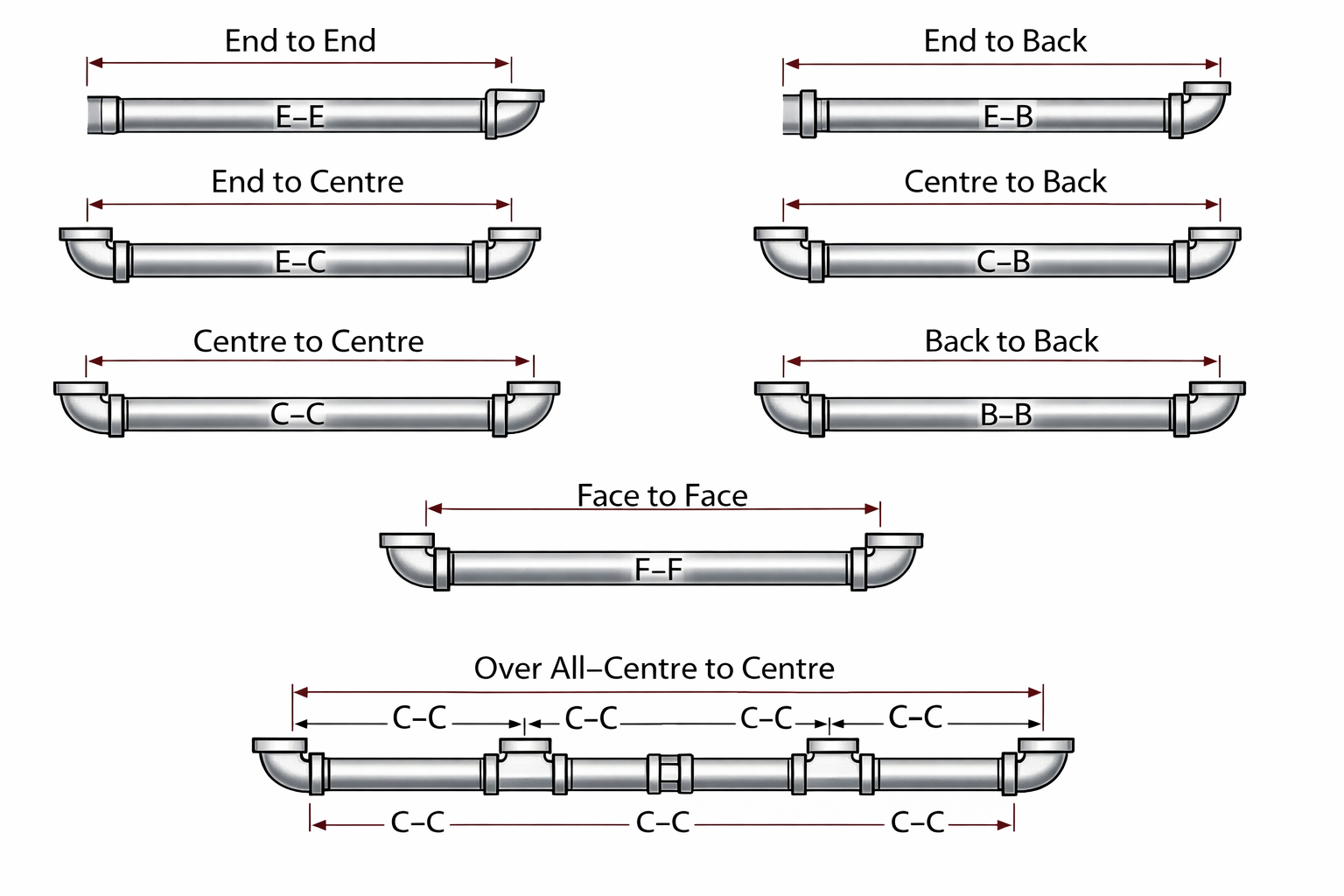
Centre-to-centre is the measurement most commonly used when laying out and installing pipe in the field. A centre-to-centre measurement is the distance from the centre of one fitting to the centre of another fitting. That distance remains the same regardless of pipe size because it is measured between fitting centres, not pipe length. However, because the fitting allowance and thread engagement vary with the size of the pipe, the cut length of the pipe will vary for different pipe sizes.
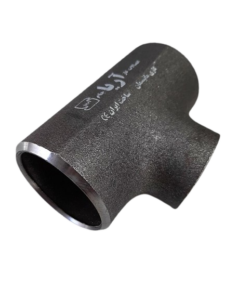
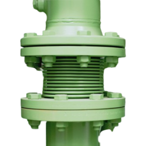
End-to-end measurements and end-to-centre measurements will sometimes be used when installing fittings that have no thread engagement (hubless fittings). With butt weld fittings and most mechanical joint fittings, the pipe does not penetrate the fitting; therefore only the throw for each fitting is considered when calculating the required cut length.
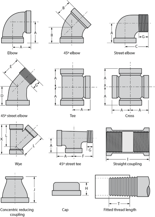
Each size and type of pipe fitting has specifications for its manufacture that are standardized throughout the industry. Most pipe trades training manuals contain tables that provide fitting specifications. For this section, you will be using IPT’s Pipe Trades Training Manual.
“Dimensions for Malleable Iron Fittings” in IPT’s Pipe Trades Training Manual (Table #48A, B Diagrams p. 181 in the February 2010 edition) shows some of the more common threaded fittings. The measurement designating the thread engagement or fitted thread length (T) for each size of pipe is in the lower right-hand corner. Their specifications are shown in the two tables that follow, one for imperial, and one for metric. The measurements indicated by letters in the drawings (A, B, C, etc.) are the throw dimensions (face to centre) for the fittings. The specifications for reducing tees and reducing elbows for threaded fittings are not included in IPT’s Pipe Trades Training Manual.
Example 1:
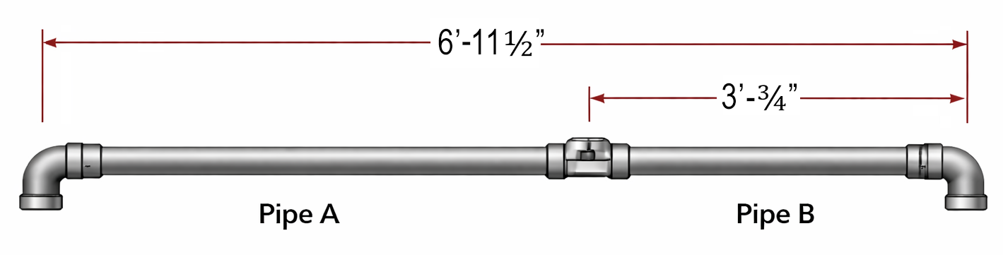
Calculate the required end-to-end lengths of the two pieces (A and B) of 1″ pipe in Figure 7 (to the nearest [latex]\frac{1}{8}\text{"}[/latex]). The 90° elbows are standard and the tee is 1″ × 1″ × 1″.
Solution:
First, obtain the unknown centre-to-centre measurement (Pipe A) from the centre-to-centre overall measurement:
[latex]\quad6\text{'} 11\frac{1}{2}\text{"} - 3\text{'} \frac{3}{4}\text{"} = 3\text{'} 10\frac{3}{4}\text{"}[/latex]
Next, obtain the proper specifications for the fittings. Table 1 gives the throw dimension for both the 90° elbows. The tee is given as dimension A, and the thread engagement is given as dimension T.
Now solve for the required fitting allowance. Table 1 gives the throw dimension A (Column A, Row 1″) as 1.5″ for both the 90° elbows and the tee. Dimension T (Column T, Row 1″) is given as 0.58″.
[latex]\quad\text{Fitting allowance} = \text{Throw} - \text{thread engagement}\\ \quad\text{FA (for 1"}\text{ 90° elbow/tee)} = 1.5\text{"} - 0.58\text{"}\\ \quad\text{FA} = 0.92\text{"}[/latex]
|
DIMENSIONS FOR MALLEABLE IRON FITTINGS (CLASS 150) |
|||||||||||||
|
Nominal Pipe Size Inches |
Dimensions – Inches |
||||||||||||
|
A |
B |
C |
D |
E |
F |
G |
H |
I |
J |
K |
L |
T |
|
|
[latex]\frac{1}{8}[/latex] |
0.69 |
– |
1.00 |
– |
– |
– |
0.26 |
0.53 |
0.96 |
– |
– |
– |
0.25 |
|
[latex]\frac{1}{4}[/latex] |
0.81 |
0.73 |
1.19 |
0.73 |
0.94 |
1.19 |
0.40 |
0.63 |
1.06 |
1.00 |
– |
– |
0.32 |
|
[latex]\frac{3}{8}[/latex] |
0.95 |
0.80 |
1.44 |
0.80 |
1.03 |
1.44 |
0.41 |
0.74 |
1.16 |
1.13 |
1.93 |
1.43 |
0.36 |
|
[latex]\frac{1}{2}[/latex] |
1.12 |
0.88 |
1.63 |
0.88 |
1.15 |
1.63 |
0.53 |
0.87 |
1.34 |
1.25 |
2.32 |
1.71 |
0.43 |
|
[latex]\frac{3}{4}[/latex] |
1.31 |
0.98 |
1.89 |
0.98 |
1.29 |
1.89 |
0.55 |
0.97 |
1.52 |
1.44 |
2.77 |
2.05 |
0.50 |
|
1 |
1.50 |
1.12 |
2.14 |
1.12 |
1.47 |
2.14 |
0.68 |
1.16 |
1.67 |
1.69 |
3.28 |
2.43 |
0.58 |
|
[latex]1\frac{1}{4}[/latex] |
1.75 |
1.29 |
2.45 |
1.29 |
1.71 |
2.45 |
0.71 |
1.28 |
1.93 |
2.06 |
3.94 |
2.92 |
0.67 |
|
[latex]1\frac{1}{2}[/latex] |
1.94 |
1.43 |
2.69 |
1.43 |
1.88 |
2.69 |
0.72 |
1.33 |
2.15 |
2.31 |
4.38 |
3.28 |
0.70 |
|
2 |
2.25 |
1.68 |
3.26 |
1.68 |
2.22 |
3.26 |
0.76 |
1.45 |
2.53 |
2.81 |
5.17 |
3.93 |
0.75 |
|
[latex]2\frac{1}{2}[/latex] |
2.70 |
1.95 |
3.86 |
1.95 |
2.57 |
– |
1.14 |
1.70 |
2.88 |
3.25 |
6.25 |
4.73 |
0.92 |
|
3 |
3.08 |
2.17 |
4.51 |
2.17 |
3.00 |
– |
1.20 |
1.80 |
3.18 |
3.69 |
7.26 |
5.55 |
0.98 |
|
[latex]3\frac{1}{2}[/latex] |
3.42 |
2.39 |
– |
– |
– |
– |
– |
1.90 |
– |
– |
– |
– |
1.03 |
|
4 |
3.79 |
2.61 |
5.69 |
2.61 |
3.70 |
5.69 |
1.30 |
2.08 |
3.69 |
4.38 |
8.98 |
6.97 |
1.08 |
|
5 |
4.50 |
3.05 |
6.86 |
– |
– |
– |
1.41 |
2.32 |
– |
– |
– |
– |
1.18 |
|
6 |
5.13 |
3.46 |
8.03 |
– |
– |
– |
1.51 |
2.55 |
– |
– |
– |
– |
1.28 |
|
NOTE: Dimensions for table are based on fittings manufactured to ANSI/ASME B16.3 Standard. |
|||||||||||||
Now calculate the length of the first piece of pipe (Pipe A). Change the measurement to decimal inches for ease of calculation. The centre-to-centre measurement includes a 90° elbow on one end and half of a tee on the other:
[latex]\quad3\text{' } 10\frac{3}{4}\text{"} = 46.75\text{"}\\ \quad\text{Length} = 46.75\text{"} - 0.92\text{" (FA tee)} - 0.92\text{" (FA elbow)} = 44.91\text{"}[/latex]
Convert back to feet, inches and fractions of an inch:
[latex]\quad44.91\text{"} = 3\text{' } 8\frac{7}{8}\text{"}[/latex]
The second piece (Pipe B) has the same allowance subtracted as the first (one 90° elbow and one tee):
[latex]\quad3\text{'}\frac{3}{4}\text{"} = 36.75\text{"}\\ \quad36.75\text{"} - (2 \times 0.92\text{"}) = 34.91\text{"} = 2\text{' } 10\frac{7}{8}\text{"}[/latex]
Example 2:
Calculate the required end-to-end length of three pieces (A, B, and C) of 50 mm pipe (to the nearest millimetre) (Figure 8). The 90° elbows are standard, and the tee is 50 mm × 50 mm × 50 mm.
First, obtain the unknown centre-to-centre measurement (Pipe A) from the centre-to-centre overall measurement:
[latex]\quad912\text{ mm} - 385\text{ mm} = 527\text{ mm}[/latex]
Next, obtain the proper specifications for the fittings from IPT’s Pipe Trades Training Manual.
Now solve for the required fitting allowance. Table 1 gives the throw dimension A (Column A, Row 50 mm) as 57.2 mm for both the 90° elbows and the tee. Dimension H (Column H, Row 50 mm) is given as 36.8 mm (throw) for the cap. Dimension T (Column T, Row 50 mm) is given as 19.1 mm (the thread engagement for any 50-mm fitting).
[latex]\quad\text{Fitting allowance} = \text{Throw} - \text{thread engagement}\\ \quad\text{FA (for 50mm 90° elbow/tee)} = 57.2\text{ mm} - 19.1\text{ mm}\\ \quad\text{FA} = 38.1\text{ mm}\\ \quad\text{FA (for 50mm cap)} = 36.8\text{ mm} - 19.1\text{ mm}\\ \quad\text{FA} = 17.7\text{ mm}[/latex]
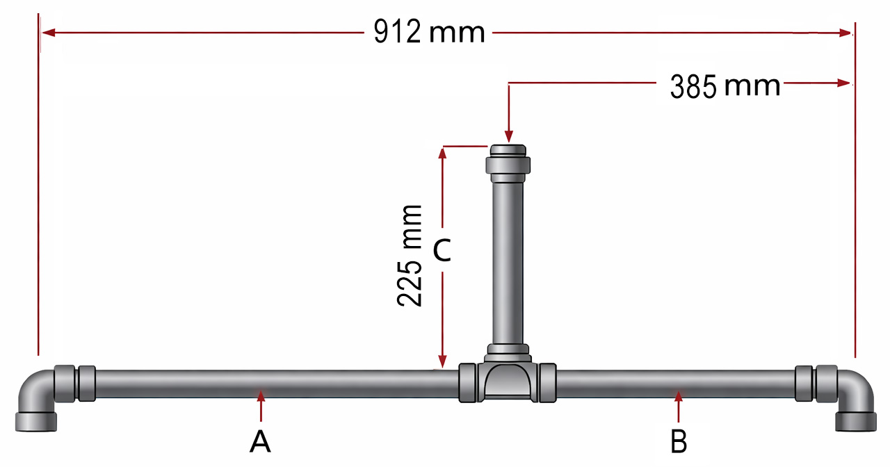
- Calculate the end-to-end length of piece A: [latex]527\text{ mm} - (2 \times 38.1\text{ mm}) = 450.8\text{ mm}[/latex]
- Calculate the end-to-end length of piece B: [latex]385\text{ mm} - (2 \times 38.1\text{ mm}) = 308.8\text{ mm}[/latex]
- Calculate the end-to-end length of the riser C: [latex]225\text{ mm} - 38.1 - 17.7 = 169.2\text{ mm}[/latex]
Example 3:
Calculate the end-to-end length of the three pieces (A, B and C) of 25 mm pipe (to the nearest millimetre). The 45° elbows and cap are standard.
Obtain the proper specifications for the fittings from IPT’s Pipe Trades Training Manual.
Note that you will be using 45° fittings and caps in this exercise, so refer to the diagrams page for the proper throw dimension.
Solve for the fitting allowance. Table 1 gives B (Column B, Row 25 mm) as 28.5 mm for both the 45° elbows. Table 1 gives H (Column H, Row 25 mm) as 29.5 mm (throw) for the cap. T (Column T, Row 25 mm) as 14.7 mm will be the thread engagement for any 25 mm fitting.
[latex]\quad\text{Fitting allowance} = \text{Throw} - \text{thread engagement}\\ \quad\text{FA 45° elbows} = 28.5\text{ mm} - 14.7\text{ mm} = 13.8\text{ mm}\\ \quad\text{FA caps} = 29.5\text{ mm} - 14.7\text{ mm} = 14.8\text{ mm}[/latex]
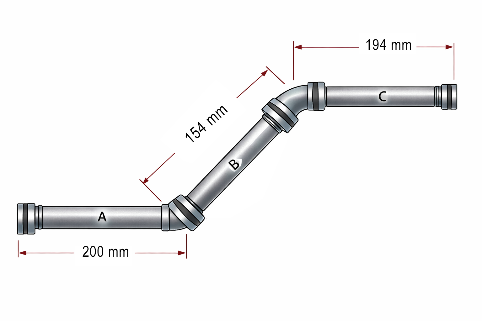
- Calculate the end-to-end length of piece A: [latex]200\text{ mm} - 13.8\text{ mm} - 14.8\text{ mm} = 171.4\text{ mm}[/latex]
- Calculate the end-to-end length of piece B: [latex]154\text{ mm} - (2 \times 13.8\text{ mm}) = 126.4\text{ mm}[/latex]
- Calculate the end-to-end length of piece C: [latex]194\text{ mm} - 13.8\text{ mm} - 14.8\text{ mm} = 165.4\text{ mm}[/latex]
Butt-Welded Pipe and Fittings
Butt-weld steel fittings are standardized in the pipe trades. An important specification for butt-weld fittings is the throw measurement. The lessons learned in this section could also be used on other types of piping materials using mechanical joint (MJ) connectors.
Fitting allowances for butt-weld pipe fittings are easier to calculate than for threaded pipe, because you do not have to allow for a thread engagement. You do, however, have to allow for weld gaps.
While the gap used for the production of a weld itself is not large ([latex]\frac{1}{8}\text{"}[/latex], [latex]\frac{3}{32}\text{"}[/latex], etc.), over a long run with a lot of fittings, the gaps add up, which can cause the piping to be too long and out of alignment if not accounted for.
Radius of a Weld Elbow
The radius of an elbow is measured from its centreline to a point that marks the centre of its bend (Figure 10). For a 90° elbow, the radius and the throw are the same.
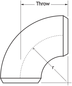
A standard 90° elbow (sometimes called a long-radius elbow) normally has a radius of 1.5 times the nominal pipe size. For example, a 2″ elbow would have a radius of 3″. Long-radius elbows are usually designated by the number of times the radius is greater than the nominal pipe size (2d, 3d, etc.). A short-radius elbow has a radius equal to the nominal pipe size.
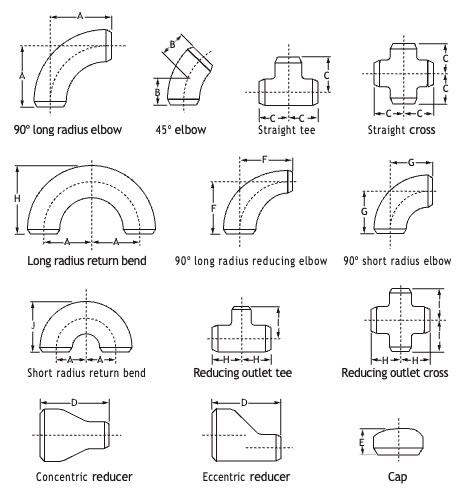
Illustration number 76 in the IPT manual (also shown in Figure 11 below) shows an assortment of the most commonly used butt-weld fittings. The measurements that correspond to the indicated throws are in Tables 53 and 54. Note that the IPT manual includes the dimensions of reducing-butt-weld tees and crosses in Tables 55 and 56.
The throw and gap of a butt-weld fitting must be subtracted from the centre-to-centre measurement to find the (end-to-end) cut length. Remember that the throw dimension is the portion of a centre-to-centre measurement that is not straight pipe.
Example 4:
Find the end-to-end cut lengths for 3″ schedule 40 piping shown in Figure 12. The 90° long-radius elbows are standard, and the specified weld gap is [latex]\frac{1}{8}\text{"}[/latex].
In Figure 11, you can see that dimension A is the measurement for the throw of a 90° long-radius elbow, and dimension E is the length of a cap. The IPT manual gives the length of A as [latex]3\text{'}\space4\frac{1}{2}\text{"}[/latex] (1.5 times the nominal pipe size) and the length for a cap as [latex]2\text{"}[/latex].
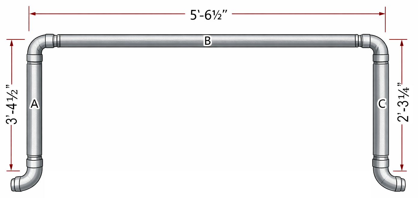
Step 1: Solve for the end-to-end length of piece A. You must subtract a throw and a weld gap from each end.
Convert to inches:
[latex]\quad3\text{' } 4\frac{1}{2}\text{"} = 40\frac{1}{2}\text{"}\\ \quad\text{A} = 40\frac{1}{2}\text{"} - \text{2 throws} - \text{2 weld gaps}\\ \quad\text{A} = 40\frac{1}{2}\text{"} - (2 \times 4\frac{1}{2}\text{"}) - (2 \times \frac{1}{8}\text{"}) = 31\frac{1}{4}\text{" or } \quad2\text{' }7\frac{1}{4}\text{"}\\[/latex]
Step 2: Solve for the end-to-end length of piece B. Convert to inches:
[latex]\quad5\text{' } 6\frac{1}{2}\text{"} = 66\frac{1}{2}\text{"}\\ \quad\text{A} = 66\frac{1}{2}\text{"} - \text{2 throws} - \text{2 weld gaps}\\ \quad\text{A} = 66\frac{1}{2}\text{"} - (2 \times 4\frac{1}{2}\text{"}) - (2 \times \frac{1}{8}\text{"}) = 57\frac{1}{4}\text{" or } 4\text{' }9\frac{1}{4}\text{"}\\[/latex]
Step 3: Solve for the end-to-end length of piece C. Convert to inches:
[latex]\quad2\text{' } 3\frac{1}{4}\text{"} = 27\frac{1}{4}\text{"}\\ \quad\text{A} = 27\frac{1}{4}\text{"} - \text{1 throw} - \text{1 cap length (E)} - \text{2 weld gaps}\\ \quad\text{A} = 27\frac{1}{4}\text{"} - 4\frac{1}{2}\text{"} - 2 - (2 \times \frac{1}{8}\text{"}) = 20\frac{1}{2}\text{" or } 1\text{' }8\frac{1}{2}\text{"}\\[/latex]
Example 5:
Find the end-to-end cut length for 50 mm schedule 40 piping (Figure 13). The 90° long-radius elbows are standard, and the specified weld gap is 3 mm.
From the table in the IPT manual you can see that dimension A is the measurement for the throw of a 90° long-radius elbow, dimension C is the measurement for the throw of a tee, and dimension E is used for the length of a cap.
The IPT manual gives the length of A as 76 mm (1.5 times the nominal ID), C as 64 mm and E as 38 mm.
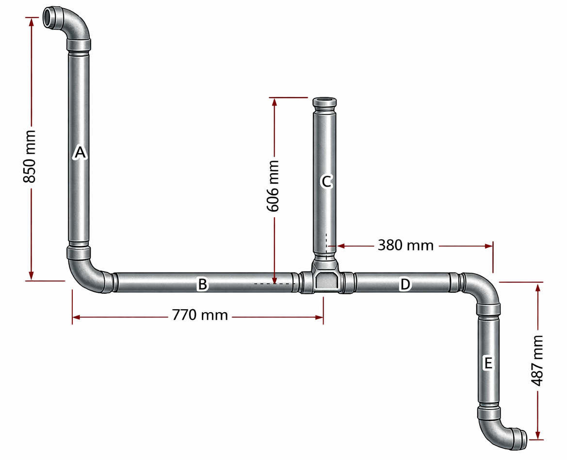
Step 1: Solve for the end-to-end length of piece A. You must subtract 2 throws (90 deg ell) and a weld gap from each end.
[latex]\quad\text{A} = 850\text{ mm} - \text{2 throws} - \text{2 weld gaps}\\ \quad\text{A} = 850\text{ mm} - (2 \times 76\text{ mm}) - (2 \times 3\text{ mm}) = 692\text{ mm}\\[/latex]
Step 2: Solve for the end-to-end length of piece B. You must subtract 1 throw (90 deg ell), 1 throw (tee) and a weld gap at each end.
[latex]\quad\text{B} = 770\text{ mm} - 76\text{ mm} - 64\text{ mm} - (2 \times 3\text{ mm}) = 624\text{ mm}\\[/latex]
Step 3: Solve for the end-to-end length of piece C. You must subtract 1 throw (tee), the length of the cap (E) and a weld gap at each end.
[latex]\quad\text{C} = 606\text{ mm} - 64\text{ mm} - 38\text{ mm} - (2 \times 3\text{ mm}) = 498\text{ mm}\\[/latex]
Step 4: Solve for the end-to-end length of piece D. You must subtract 1 throw (90 deg ell), 1 throw (tee) and a weld gap at each end.
[latex]\quad\text{D} = 380\text{ mm} - 76\text{ mm} - 64\text{ mm} - (2 \times 3\text{ mm}) = 234\text{ mm}\\[/latex]
Step 5: Solve for the end-to-end length of piece E. You must subtract 2 throws (90 deg ell) and a weld gap from each end.
[latex]\quad\text{E} = 487\text{ mm} - (2 \times 76\text{ mm}) - (2 \times 3\text{ mm}) = 329\text{ mm}\\[/latex]
Socket-Weld Fittings
Socket-weld fittings are used to join smaller sizes of pipe, usually 2″ and under, that require the strength and security of a welded joint. Like threaded fittings, socket-weld fittings have a length of pipe that fits into the fitting, meaning that the throw and the fitting allowance have two different values. Calculating the end-to-end measurements for socket-weld fittings is more complex because a small gap must be left between the pipe and the bottom of the socket. (Figure 14).
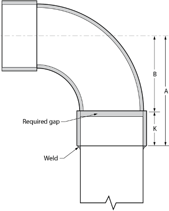
This gap is required to allow for expansion of the pipe in the fitting. If the pipe were to bottom out in the fitting, a large temperature change might cause the pipe to expand enough to break the weld. The gap mentioned in the IPT manual is [latex]\frac{1}{16}\text{"}[/latex] or 1.6 mm, but it may be different, depending on the job specifications.
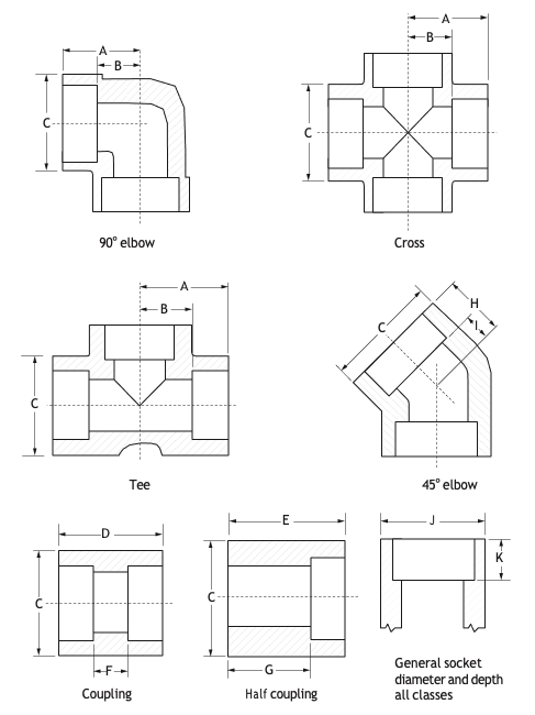
The diagrams in Tables 51 and 52 in the IPT manual show an assortment of the most commonly used socket-weld fittings (also shown in Figure 15 below). The measurements that correspond to the indicated throws are on the following pages. Along with the throw (dimension A) of the fitting, the fitting allowance (dimension B, which already includes a [latex]\frac{1}{16}\text{"}[/latex] gap) is given. Socket depth is given as dimension K in the lower right-hand corner, which could be used if the job specifies a different gap dimension.
Example 6:
Find the end-to-end cut lengths for the four pieces of pipe shown in Figure 16. The fittings are [latex]1\frac{1}{4}\text{"}[/latex], 3,000#, schedule 80. The specified weld gap is [latex]\frac{1}{16}\text{"}[/latex].
From the table in the IPT manual you can see that dimension B is the measurement for the fitting allowance of a 90° elbow and a tee (gap included). The IPT manual gives the length of dimension B as 1.06″.
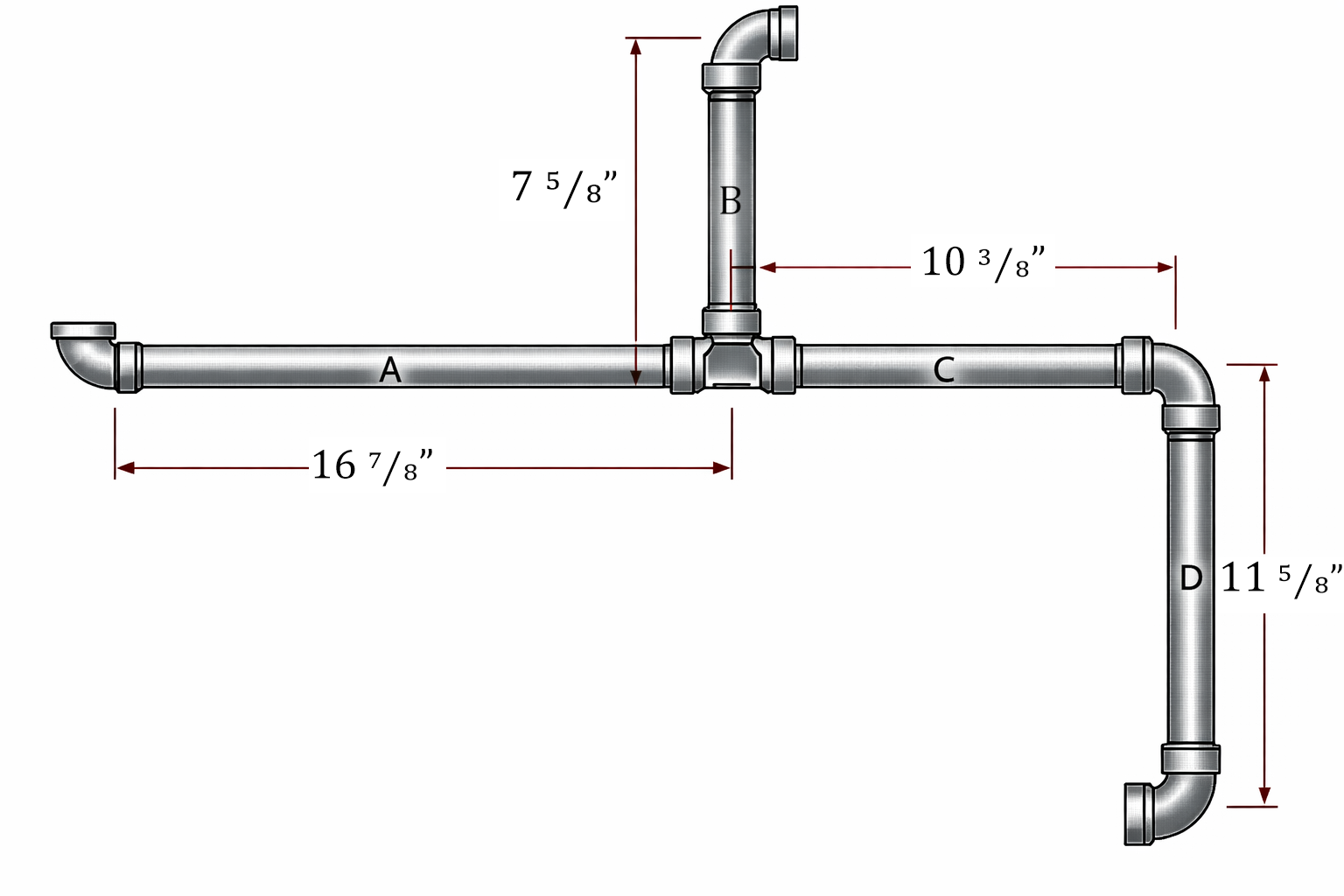
Step 1: Solve for the end-to-end length of piece A. You must subtract 2 fitting allowances (90 deg ell and tee).
Step 2: Convert the fitting allowance given to the fractional equivalent.
[latex]\quad\text{Fitting allowance} = 1.06\text{"} = 1\frac{1}{16}\text{"}\\ \quad\text{A} = 16\frac{7}{8}\text{"} - 2\text{ fitting allowances}\\ \quad\text{A} = 16\frac{7}{8}\text{"} - (2 \times 1\frac{1}{16}\text{"})\\ \quad\text{A} = 16\frac{7}{8}\text{"} - 2\frac{1}{8}\text{"} = 14\frac{3}{4}\text{"}\\[/latex]
Step 3: Solve for the end-to-end length of piece B. You must subtract 2 fitting allowances (90 deg ell and tee).
[latex]\quad\text{B} = 7\frac{5}{8}\text{"} - 2\text{ fitting allowances}\\ \quad\text{B} = 7\frac{5}{8}\text{"} - (2 \times 1\frac{1}{16}\text{"})\\ \quad\text{B} = 7\frac{5}{8}\text{"} - 2\frac{1}{8}\text{"} = 5\frac{1}{2}\text{"}\\[/latex]
Step 4: Solve for the end-to-end length of piece C. You must subtract 2 fitting allowances (90 deg ell and tee).
[latex]\quad\text{C} = 10\frac{3}{8}\text{"} - 2\text{ fitting allowances}\\ \quad\text{C} = 10\frac{3}{8}\text{"} - (2 \times 1\frac{1}{16}\text{"})\\ \quad\text{C} = 10\frac{3}{8}\text{"} - 2\frac{1}{8}\text{"} = 8\frac{1}{4}\text{"}\\[/latex]
Step 5: Solve for the end-to-end length of piece D. You must subtract 2 fitting allowances (90 deg ell).
[latex]\quad\text{D} = 11\frac{5}{8}\text{"} - 2\text{ fitting allowances}\\ \quad\text{D} = 11\frac{5}{8}\text{"} - (2 \times 1\frac{1}{16}\text{"})\\ \quad\text{D} = 11\frac{5}{8}\text{"} - 2\frac{1}{8}\text{"} = 9\frac{1}{2}\text{"}\\[/latex]
Example 7:
Find the end-to-end cut lengths of the six pieces of pipe shown in Figure 17. The fittings are 25 mm, 6,000#, schedule 160. The specified weld gap is 1.6 mm.
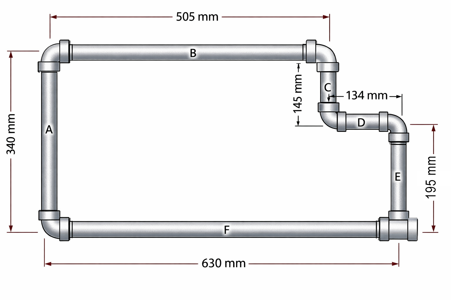
Step 1: Solve for the end-to-end length of piece A. You must subtract 2 fitting allowances (90 deg ell).
[latex]\quad\text{A} = 340\text{ mm} - 2\text{ fitting allowances}\\ \quad\text{A} = 340\text{ mm} - (2 \times 26.92\text{ mm})\\ \quad\text{A} = 340\text{ mm} - 53.84\text{ mm} = 286.16\text{ mm}\\[/latex]
Step 2: Solve for the end-to-end length of piece B. You must subtract 2 fitting allowances (90 deg ell).
[latex]\quad\text{B} = 505\text{ mm} - 2\text{ fitting allowances}\\ \quad\text{B} = 505\text{ mm} - (2 \times 26.92\text{ mm})\\ \quad\text{B} = 505\text{ mm} - 53.84\text{ mm} = 451.16\text{ mm}\\[/latex]
Step 3: Solve for the end-to-end length of piece C. You must subtract 2 fitting allowances (90 deg ell).
[latex]\quad\text{C} = 145\text{ mm} - 2\text{ fitting allowances}\\ \quad\text{C} = 145\text{ mm} - (2 \times 26.92\text{ mm})\\ \quad\text{C} = 145\text{ mm} - 53.84\text{ mm} = 91.16\text{ mm}\\[/latex]
Step 4: Solve for the end-to-end length of piece D. You must subtract 2 fitting allowances (90 deg ell).
[latex]\quad\text{D} = 134\text{ mm} - 2\text{ fitting allowances}\\ \quad\text{D} = 134\text{ mm} - (2 \times 26.92\text{ mm})\\ \quad\text{D} = 134\text{ mm} - 53.84\text{ mm} = 80.16\text{ mm}\\[/latex]
Step 5: Solve for the end-to-end length of piece E. You must subtract 2 fitting allowances (90 deg ell and tee).
[latex]\quad\text{E} = 195\text{ mm} - 2\text{ fitting allowances}\\ \quad\text{E} = 195\text{ mm} - (2 \times 26.92\text{ mm})\\ \quad\text{E} = 195\text{ mm} - 53.84\text{ mm} = 141.16\text{ mm}\\[/latex]
Step 6: Solve for the end-to-end length of piece F. You must subtract 2 fitting allowances (90 deg ell and tee).
[latex]\quad\text{F} = 630\text{ mm} - 2\text{ fitting allowances}\\ \quad\text{F} = 630\text{ mm} - (2 \times 26.92\text{ mm})\\ \quad\text{F} = 630\text{ mm} - 53.84\text{ mm} = 576.16\text{ mm}\\[/latex]
Tube and Tubing
Tube and tubing are commonly joined by soldering or compression joints. Calculations for making these joints are similar to socket-weld joints in that these joints have a pipe engagement rather than a thread engagement. However, the joints do not have a weld gap, and the pipe is engaged to the shoulder of the fitting before soldering or compression.

Self-Test C-1.7.1: Calculate Piping Measurements
Complete Self-Test C-1.7.1 and check your answers.
If you are using a printed copy, please find Self-Test C-1.7.1 and Answer Key at the end of this section. If you prefer, you can scan the QR code with your digital device to go directly to the interactive Self-Test.
Grade, Elevation, and Benchmarks
It is often necessary to install drainage pipe with a slope so that liquids may flow by gravity to a sewer, sump or drain point. Condensate lines and steam return mains must achieve minimum slope in order to function properly. Ensuring proper slope, or grade, in a drainage system is very important for the system to function properly. If the piping doesn’t have enough grade, drains could run slowly and blockage problems could arise. If the piping has too much grade, the pipe could be too low in elevation, and it would become impossible to connect the building sewer to the public sewer in the street.
The term grade refers to a vertical distance (rise or fall) divided by the horizontal distance (run). When a grade is specified on a drawing (for example, 1:50), it means that for 50 feet of run in the horizontal direction, there will be a 1-foot vertical drop, resulting in a downward slope in the direction of flow. In this way, the specified grade is stated as a ratio of the rise over run.
Another important skill used in the piping trades is being able to determine the height (elevation) and location at which piping is to be located in and below a building.
On some job sites, there may be no single source for this information. Elevation information may be given on a drawing, may have to be calculated from available information, or may even have to be determined on the job site with physical measurements.
Grade
In the construction trades, grade is used to determine the degree of rise or fall of a sloping surface such as a ramp or a roof pitch. Within the pipe trades, the slope of a pipe is expressed as the amount of grade (slope) the pipe has on it. Grade is usually expressed in one of three ways:
- Fraction of an inch per foot: For example, [latex]\frac{\frac{1}{4}\text{"}}{\text{ ft.}}[/latex] means that for every 1 foot of length or run the pipe is going to slope up or down [latex]\frac{1}{4}\text{"}[/latex]. The National Plumbing Code specify a minimum grade of [latex]\frac{1}{4}\text{"}[/latex] per foot or 1:50 on all drainage piping 3″ and less in diameter.
- Percentage of length as compared to the rise or drop: For example, 1% means that for every unit of length the pipe is going to slope up or down 1%. This method is appropriate for both imperial and metric units.
- Ratio of the drop or rise to the length: For example, 1:50 means for every 50 units of length the pipe will slope up or down 1 unit. This method is appropriate for both imperial and metric units.
There are many times when the same grade can be written in different ways. Although these grades are expressed in different forms, they all refer to the amount of fall for each measurement length of piping.
Examples:
1% grade:
- 1% grade = 1 foot of drop for 100 feet of run
- 1:100 grade = 1 foot of drop for 100 feet of run
- [latex]\frac{\frac{1}{8}\text{"}}{\text{ ft.}}[/latex] is approx. 1 foot of drop for 100 feet of run. (More accurately = 1-foot drop in 96-foot run)
2% grade:
- 2% grade = 1 foot of drop for 50 feet of run
- 1:50 grade = 1 foot of drop for 50 feet of run
- [latex]\frac{\frac{1}{4}\text{"}}{\text{ ft.}}[/latex] is approx. 1 foot of drop for 50 feet of run. (More accurately = 1-foot drop in 48-foot run)
Calculating Total Fall
There are three factors you must consider when calculating grade problems (Figure 18): the length or run of the pipe, the grade on the pipe and the total fall of the pipe. In drainage systems, total fall is the distance the nominally horizontal pipe falls over a given length of pipe at a given grade.
It is important to always include the units of measurement in the calculation, as they are the best indicator of the correctness of your answer. If the answer has unfamiliar units, it is probably incorrect. It is especially important to keep the units in calculations using fractions per foot because some of the units will cancel out.
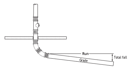
The formula for calculating total fall is:
[latex]\quad\text{Total fall} = \text{Grade} \times \text{Run}[/latex]
This formula can be placed into a formula triangle and any unknown can be calculated (Figure 19)
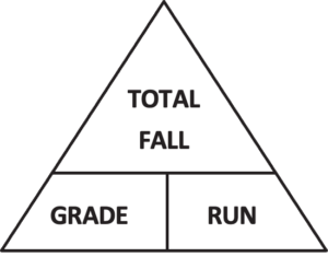
[latex]\quad\text{Total Fall} = \text{Grade} \times \text{Run}\\ \quad\text{Grade} = \frac{\text{Total Fall}}{\text{Run}}\\ \quad\text{Run} = \frac{\text{Total Fall}}{\text{Grade}}[/latex]
Of the three factors mentioned above, at least two must be known before the third can be calculated.
Tip: Always check your units. If your answer is in the wrong unit (for example, feet instead of inches), the calculation is likely incorrect.
Fraction per Foot Calculations
When you are solving a problem and the grade is provided as a fraction of an inch per foot of run, the total fall must be expressed in inches and the length must be expressed in feet.
Example 1:
Calculate the total fall of a sewer line 150′ long and with a grade of [latex]\frac{1}{4}\text{"}[/latex] per foot.
[latex]\quad\text{Total fall (in inches)} = \text{Grade (in inches per foot)} \times \text{Run (in feet)}[/latex]
Solution:
[latex]\quad\text{Total Fall} = \text{Grade} \times \text{Run}\\ \quad\text{Total Fall} = \frac{\frac{1}{4}\text{"}}{\text{ ft.}} \times 150\text{ ft.} =\\ \space\space\space\space\text{Total Fall} = \frac{0.25\text{"}}{\text{ ft.}} \times 150\text{ ft.} = 37.5\text{"}[/latex]
Answer:
Total fall is 37.5″ over the run of 150′.
Note: The run or length of the pipe is 150 FEET while the total fall is in INCHES.
Example 2:
Find the grade on an 80′ long sewer line that has a total fall of 10″.
[latex]\quad\text{Grade (in inches per foot)} = \frac{\text{Total fall (in inches)}}{\text{Run (in feet)}}[/latex]
Solution:
[latex]\quad\text{Grade} = \text{Total Fall} \times \text{Run}\\ \quad\text{Total Fall} = \frac{10\text{"}}{80\text{ ft.}} = \frac{0.125\text{"}}{\text{ ft.}} = \frac{\frac{1}{8}\text{"}}{\text{ ft.}}[/latex]
Answer:
The grade on the pipe is [latex]\frac{\frac{1}{8}\text{"}}{\text{ ft.}}[/latex].
Example 3:
Find the length of a sewer line when the grade is [latex]\frac{3}{16}\text{"}[/latex] per foot and the total fall is [latex]22\frac{1}{2}\text{"}[/latex].
Note: This is an example where the total fall is given and the grade is given. In this case we have to solve for the run.
[latex]\quad\text{Run (in feet)} = \frac{\text{Total fall (in inches)}}{\text{Grade (in inches per foot)}}[/latex]
Solution:
[latex]\quad\text{Run} = \text{Total Fall} \times \text{Grade}\\ \quad\text{Run} = \frac{22.5\text{"}}{\frac{3}{16}/\text{ ft.}} = \frac{22.5\text{"}}{0.1875\text{"}/\text{ ft.}} = 120\text{ ft.}[/latex]
Answer:
The length of the pipe is 120 ft.
Percentage Calculations
Unlike fraction calculations, which are used only in the imperial system, percentage calculations can be used for either imperial or metric measurements. Similarly, the units of length and fall in percentage problems are not going to vary. If you are solving for the total fall and start with a length in metres, you will end up with an answer (for total fall) in metres. If you are solving for the length and start with a total fall in millimetres, you will end up with an answer (for length) in millimetres, and so on.
Example 1:
A 75-m length of piping is to be graded down at 2%. Calculate the amount of fall over the entire length of the pipe.
Solution:
[latex]\begin{aligned} \text{TF} &= \text{Grade}\times \text{Length}\\ &= 75\,\text{m} \times 2\%\\ &= 75\,\text{m} \times 0.02\\ &= 1.5\,\text{m} \end{aligned}[/latex]
Answer:
The total fall is 1.5 m or 1,500 mm.
Example 2:
A building sewer falls 400 mm over its length. It is graded at 1%. Calculate the length of the run.
Solution:
[latex]\quad\text{Length} = \frac{\text{TF}}{\text{Grade}}\\ \quad\text{Length} = \frac{400\text{ mm}}{0.01}=40,000\text{ mm}\\ \quad\text{Length} = 40,000\text{ mm}[/latex]
Answer:
The length is 40,000 mm or 40 m.
Example 3:
A pipeline falls 750 mm over its length of 50 m. Calculate the percentage grade at which the line is sloped.
Solution:
First, change to the same units:
[latex]\quad50\text{ m} = 50,000 \text{ mm}[/latex].
Percentage calculations represent comparisons of the same units, and therefore require that all units be expressed in equal terms.
[latex]\begin{aligned} \text{Grade} &= \frac{\text{TF}}{\text{Length}}\\ &= \frac{750\,\text{mm}}{50{,}000\,\text{mm}}\\ &= 0.015\\ &= 1.5\% \end{aligned}[/latex]
Answer:
The grade on the pipe is 1.5%.
Ratio Calculations
Much like percentage calculations, ratio calculations can be used for either imperial or metric measurements. Ratios can be written and treated exactly the same as a fraction. When grades are expressed as ratios (e.g., 1:50 or [latex]\frac{1}{50}[/latex]), the answer will be in the same units of measure that are being used for the known dimension (feet, inches, metres, centimetres, etc.). Ratio grades are defined as the ratio of fall per unit of length. For example, a pipe graded at 1:50 will fall 1 unit of measure for every 50 units of measure of length or run.
Example 1:
A pipe is to be graded at 1:50. The length of the run is to be 25 metres. Calculate the fall on the entire pipe.
Solution:
The pipe will have a total fall equal to [latex]\frac{1}{50}[/latex] of its total length.
[latex]\quad\text{TF} = \text{Grade} \times \text{Length}\\ \quad\text{TF} = \frac{1\text{ m}}{50\text{ m}} \times 25\text{ m}\\ \quad\text{TF} = 0.5\text{ m}[/latex]
Answer:
The total fall on the pipe is 0.5 m or 500 mm.
Example 2:
A line graded at 1:133 has a drop (fall) over its entire length of 700 mm. Calculate the length of the run.
Solution:
[latex]\quad\text{Length} = \frac{\text{TF}}{\text{Grade}}\\ \quad\text{Length} = \frac{700\text{ mm}}{\frac{1}{133}}=700 \times \frac{133}{1} = 93,100\text{ mm}\\ \quad\text{Length} = 93,100\text{ mm}[/latex]
Answer:
The length on the pipe is 93,100 mm or 93.1 m.
Example 3:
A pipe falls 51″ over its entire length of 425′. Calculate the ratio grade on the pipe.
Solution:
Convert to the length of the run into inches (or the fall on the pipe into feet) to remain in same units for the calculation:
[latex]\quad425\text{ feet} \times \frac{12 \text{ inches}}{1 \text{ ft.}} = 5,100\text{ inches}\\ \quad\text{Length} = 5,100\text{"}\\ \quad\text{Grade} = \frac{\text{TF}}{\text{Length}}\\ \quad\text{Grade} = \frac{51}{5,100\text{"}} = \frac{1}{100} = 1:100[/latex]
Answer:
Grade on the pipe is 1:100.
Elevation
An elevation is the distance above or below a fixed point. On construction sites the architect may specify building elevations based on a reference point called the benchmark. The benchmark is some non-moving spot on the job site such as the street curb or a manhole cover.
Normally the main subfloor is assigned a reference elevation such as 100.00 metres or 100.00 feet, depending on the units used on the project. For example, if the main subfloor (elev. = 100.00′) was to be 2 feet above the curb (or the chosen benchmark), then the site benchmark would be given the elevation of 98.00 feet. Since all subsequent elevations are related to the subfloor, the architectural elevation for the “top of plate” at the ceiling (see Figure 20) would be 100.00′ plus 8.00′, or 108.00′.
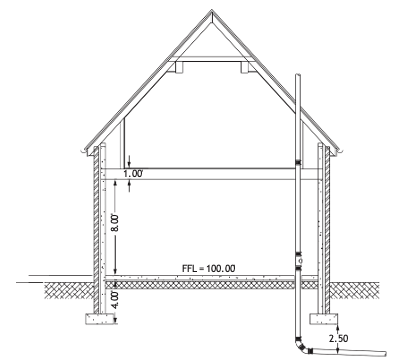
The elevation of the second floor would be 109.00′ due to the 1.00′ depth of the floor joists and the floor sheeting above it. The elevation of the bottom of the footing would be 96.00′, and the trench bottom for the building drain would be 93.50′.
Tradespeople use the project benchmark to establish the subsurface elevations because some parts of systems must be installed before the main floor is poured. Once the structure progresses above the main floor the tradesperson has a choice to use the main floor, elevation, or the benchmark for their reference point, whichever is more convenient.
In order to determine the elevations on the construction project, a pipe trades worker would use a builder’s level. Using a builder’s level requires you to know how to calculate elevations from a benchmark or from a previously calculated elevation. Most often, the level is set up in one spot and all of the readings are taken from that location. Sometimes, the level must be moved many times, using previous sightings to calculate new elevations. When this happens, accuracy in readings and calculations becomes even more important.
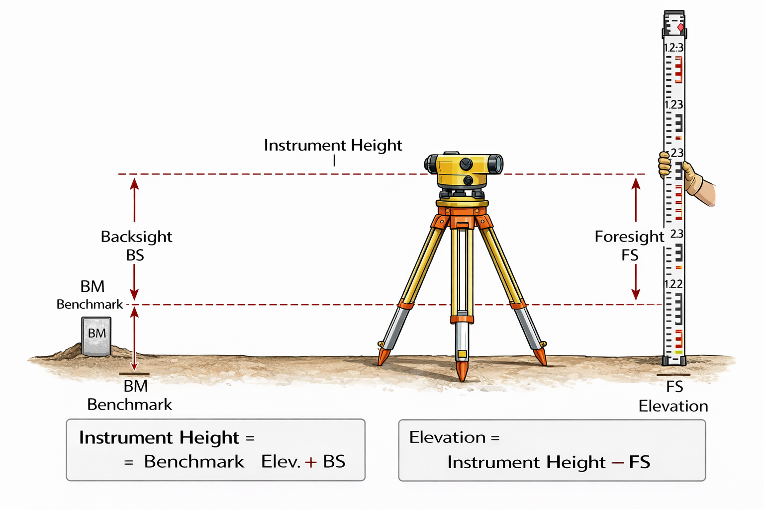
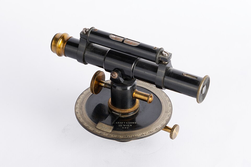
Land or geographic elevations are distances above or below mean sea level. When large projects are constructed and a local benchmark is impractical (e.g., a residential subdivision), geodetic elevations are used. When geodetic elevations are used on a building project, it is sometimes beneficial to omit the first one or two digits of the elevation to make calculations easier. When these digits are omitted, the elevation is referred to as modified or abbreviated geodetic.
Invert Level of a Pipe
In addition to slope and length, tradespeople must also determine the exact vertical position of piping. This is done using elevation and invert measurements. The invert level of a pipe is the elevation measured at the bottom inside surface of the pipe (see Figure 23). This is the lowest point inside the pipe where fluid flows.
When working with pipe elevations, tradespeople do not measure to the top or centre of the pipe. Instead, they measure to the invert because it represents the actual flow line of the system.
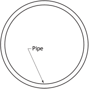
In drainage and piping systems, the invert is used because it ensures:
- Proper flow of water or waste
- Correct pipe slope (grade)
- Accurate installation elevations
Even small errors in invert elevation can cause problems such as poor drainage, standing water, or system failure.
All pipe elevations are measured from a reference point, such as a benchmark or main floor elevation. The invert elevation tells you how high or low the pipe must be installed relative to that reference. For example: If the benchmark elevation is 98.00 ft and the invert of a pipe must be installed at 95.50 ft, the pipe will be positioned 2.50 ft below the benchmark.
Practical Application:
When installing a building drain, the required slope may be specified (e.g., [latex]\frac{1}{4}[/latex]″ per foot). The tradesperson will:
- Determine the starting invert elevation.
- Calculate the required drop over distance.
- Set the ending invert elevation.
All measurements are taken from the invert, not the top of the pipe.
Invert = bottom inside of pipe (flow line)
Centre = middle of pipe
Crown = top inside of pipe
The following example shows how slope and invert are used together in real trade applications.
Example (Slope and Invert Calculation):
A building drain must be installed with a slope of [latex]\frac{1}{4}\text{" per foot}[/latex]. The pipe runs 20 ft from the building to the main.
The starting invert elevation at the building is 95.50 ft. Find the required invert elevation at the end of the pipe.
Step 1: Calculate Total Drop
Slope tells us how much the pipe must drop per foot of length.
[latex]\begin{aligned} \text{Total Drop} &= \text{slope} \times \text{length} \\ \text{Total Drop} &= \frac{1}{4}\,\text{" per foot} \times 20\,\text{ft} \\ &= 5\,\text{"} \end{aligned}[/latex]
Step 2: Convert Inches to Feet
Because elevations are in feet, convert 5 inches to feet:
[latex]\begin{aligned} 5\, \text{"} &= \frac{5}{12}= 0{.}417\, \text{ft (rounded)} \end{aligned}[/latex]
Step 3: Calculate Ending Invert Elevation
[latex]\begin{aligned} \text{Ending invert} &= 95{.}50 - 0{.}417 \text{ ft} = 95{.}08 \text{ (rounded)} \end{aligned}[/latex]
Answer: The required invert elevation at the end of the pipe is 95.08 ft. (See Figure 24.)
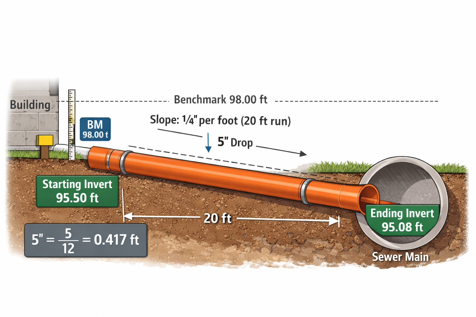
This calculation ensures that:
- The pipe has the correct slope for drainage.
- Water flows properly through the system.
- The pipe is installed at the correct elevation relative to the benchmark.
Converting Between Engineer’s Measure and Builder’s Measure
Elevations can be expressed in both metric and imperial dimensions. In the metric system, calculations are straightforward, with centimetres or millimetres typically used as the smallest unit of measurement. In the imperial system, surveyors and civil engineers often use elevation measurements in feet and decimal parts of a foot. One one-hundredth (0.01) of a foot is the smallest elevation difference. Trades workers, however, often use tape measures marked in feet, inches, and fractions of an inch to the nearest [latex]\frac{1}{16}\text{"}[/latex]. Because both systems are used in the trades, it is often necessary to convert between engineer's measure (decimal feet) and builder's measure (feet, inches and fractions of an inch) when working with elevations.
Most shops have conversion charts that give the conversions between the metric and imperial systems most useful to your trade. Specification guides will usually give you both metric and imperial measurements if appropriate. Your calculator may also have the capacity to convert between the two systems. Read your calculator’s instructions carefully; ask your instructor if you need help in figuring out how to use this feature.
Example:
Convert the decimal 14.37 ft. into feet and inches to the nearest [latex]\frac{1}{16}[/latex] of an inch.
Step 1: The 14 is a whole number and is already expressed in feet. Whole feet before the decimal require no conversion; therefore set the 14 aside as “14 feet” in your calculation.
Step 2: Start with the decimal 0.37. This is the number that you want to convert to inches and fractions of an inch.
Step 3: Multiply 0.37 by 12 to convert to inches:
[latex]\quad0.37 \times 12 = 4.44[/latex]
The whole number 4 represents whole inches. Whole inches before the decimal require no conversion. Set the number 4 aside as “4 inches” in your calculation.
Step 4: Multiply the decimal parts of an inch, 0.44, by 16 (the denominator commonly chosen if not otherwise specified) to solve for [latex]\frac{1}{16}\text{"}[/latex]:
[latex]\quad0.44 \times 16 = 7.04[/latex]
This illustrates that 0.44 of an inch (in decimal form) is equal to exactly 7.04 sixteenths of an inch. For practical purposes, round off 7.04 to the nearest whole number (7) to solve for the closest sixteenth, giving you [latex]\frac{7}{16}[/latex] of an inch.
Step 5: Put together the results of each equation to total:
[latex]\quad\text{14 feet, 4 and } \frac{7}{16}\text{ inches}[/latex]
Converting feet, inches and fractions of an inch to feet and decimal parts of a foot is the reverse of the earlier procedure.
Example:
Convert 14 feet, 4 and [latex]\frac{7}{16}[/latex] inches into feet and decimal parts of a foot.
Step 1: The 14 is a whole number, and it is already expressed in feet. Whole feet before the decimal require no conversion, so set the 14 aside as “14 feet” in your calculation.
Step 2: Convert [latex]\frac{7}{16}[/latex] of an inch into a decimal of an inch by dividing the numerator into the denominator:
[latex]\quad\frac{7}{16} \text{ of an inch } = 0.4375 \text{ of an inch, therefore } 4\frac{7}{16}\text{ inches }= 4.4375\text{ inches}[/latex]
Step 3: Divide 4.4375 inches by 12 to determine the decimal foot equivalent:
[latex]\quad\frac{4.4375 \text{ inches}}{12 \text{ inches per foot}} = 0.3698 \text{ of a foot.}[/latex]
Round to the nearest two decimals (to represent tens and hundredths of feet) to get 0.37 feet.
Step 4: Add 14 whole feet to the result you obtained in step 3, 0.37. The total is 14.37 feet.
Sample Problems and Solutions
- Convert [latex]8\text{' } 4\frac{5}{8}\text{" }[/latex] to engineer’s measure.
[latex]\quad\space8\text{'} = 8.00\text{'}\\ \quad4\frac{5}{8}\text{"} = 4.625\text{"}\\ \quad\frac{4.625}{12 \frac{\text{ in.}}{\text{ ft.}}} = 0.38\text{'}\\ \quad\therefore 8\text{' } 4\frac{5}{8}\text{"} = 8.00\text{'} + 0.38\text{'}\\ \quad= 8.38\text{'}[/latex]
- Convert 94.28′ to a builder’s measure.
[latex]\quad94\text{'} = 94.00\text{'}\\ \quad0.28\text{'} = 0.28\text{'} \times 12 \frac{\text{ in.}}{\text{ ft.}} = 3.36\text{"}\\ \quad3.36 = 3\text{"} + (0.36\text{"} \times 16) = 3\frac{6}{16}\text{"} = 3\frac{3}{8}\text{"}\\ \quad\therefore 94.28\text{' } = 94\text{' } 3\frac{3}{8}\text{"}[/latex]
- The benchmark is 100.00 feet elevation. The basement floor is 94.70 feet elevation. The first floor is 102.95 feet elevation.
- How far below the benchmark is the basement floor?
[latex]\quad100.00\text{'} − 94.70\text{' } = 5.30\text{' or } 5\text{' } 3\frac{5}{8}\text{" below benchmark}[/latex]
-
- How far above the benchmark is the first floor?
[latex]\quad102.95\text{'} − 100.00\text{'} = 2.95\text{' or } 2\text{' } 11\frac{3}{8}\text{" above benchmark}[/latex]
-
- How far is it from the basement floor to the first floor?
[latex]\quad102.95\text{'} − 94.70\text{'} = 8.25\text{' or } 8\text{' } 3\text{" between basement and first floors}[/latex]
- A house drain has a run of 30 feet at a grade of [latex]\frac{1}{8}[/latex] inch per foot. The low end has elevation of 93.50 feet. What elevation is the high end?
[latex]\quad30\text{'} \times \frac{1}{8}\text{"} = 3\frac{3}{4}\text{"} \text{ difference in elevation}\\ \quad93.50 = 93\text{' } 6\text{"}\\ \quad93\text{' } 6\text{"} + 3\frac{3}{4}\text{"} = 93\text{' } 9\frac{3}{4}\text{"}[/latex]
Self-Test C-1.7.2: Grade, Elevation, and Benchmarks
Complete Self-Test C-1.7.2 and check your answers.
If you are using a printed copy, please find Self-Test C-1.7.2 and Answer Key at the end of this section. If you prefer, you can scan the QR code with your digital device to go directly to the interactive Self-Test.
Notes for Question 29:
- Main line (pipe sections 1 & 4) are 12″ in diameter
- Branch line (pipe sections 2, 3, 5 & 6) are 6″ in diameter
- Grade on all pipe sections is [latex]\frac{\frac{1}{8}\text{"}}{\text{ft.}}[/latex]
Sump:
- Liquid depth = 24″
- Inlet is 4″ higher than outlet
- Sump height = 60″
Catch basin:
- Liquid depth = 18″
- Catch basin height = 36″ Pipe lengths:
- Main sections:
▸ Pipe section 1 = 30′
▸ Pipe section 4 = 125′
- Branches:
▸ Pipe section 2 = 75′
▸ Pipe section 3 = 21′
▸ Pipe section 5 = 40′
▸ Pipe section 6 = 64′
Remember: The invert level of a pipe is the level taken from the bottom inside of the pipe (Figure 23).
References
BCcampus. (n.d.). Playlist: Tools and equipment videos. BCcampus MediaSpace. https://media.bccampus.ca/playlist/details/0_3g8xp22x/categoryId/175673 Playlist Details – Trades Access Common Core Line C: Tools and Equipment Videos – BCcampus
BC Industry Training Authority. (2019). Piping trades apprenticeship program: Use Tools and Equipment—Level 1 harmonized [Binder]. Crown Publications, Queen’s Printer for British Columbia. https://www.crownpub.bc.ca/Product/Details/7960000261_S
- Plumber: Competency C-1 Use Mathematics and Science
- Steamfitter: Competency C-1 Use Mathematics and Science
- Sprinkler Fitter: Competency C-1 Use Mathematics and Science
Camosun College. (2019). Line C: Tools and Equipment—Competency D-1: Solve Trades Mathematical Problems (Rev. ed.) [Learning guide]. BCcampus. https://collection.bccampus.ca/textbook/qFKGAJ78/
Camosun College. (2015). Trades Access Common Core Competency D-1: Solve Trades Mathematical Problems. Victoria, B.C.: Crown Publications. Download for free from the B.C. Open Textbook Collection (https://open.bccampus.ca/browse-ourcollection/find-open-textbooks/).
Camosun Innovates. (2022). Tools and Equipment Videos [Video playlist]. Camosun College/BCcampus. https://camosuninnovates.opened.ca/
Lee, R. A. (2006). IPT’s pipe trades handbook and training manual (Rev. ed.). IPT Publishing & Training Ltd. https://iptbooks.com/product/pipe-trades-handbook/?v=5435c69ed3bc
Media Attributions
All figures are sourced from Industry Training Authority (2019) and/or Camosun College (2019) and are used under the Creative Commons Attribution 4.0 (CC BY 4.0) licence unless otherwise noted. Images copyrighted by the BC Industry Training Authority are licensed under a Creative Commons Attribution-NonCommercial-ShareAlike 4.0 (CC BY-NC-SA 4.0) licence.
- Figure 2 Pipe assembly with elbow and tee fittings was created by TRU Open Press using OpenAI, 2026, and has a CC BY-NC-SA 4.0 license.
- Figure 3 Butt weld fittings by Ghasemimoshref on Wikimedia Commons was used/adapted under a CC BY-SA 4.0 license.
- Figure 4 Mechanical joint fittings by ThisIsEngineering from Pexels was used/adapted under the Pexels License.
- Figure 6 Dimensions for malleable iron fittings, adapted from Lee (2010, p. 181), IPT Pipe Trades Training Manual, © IPT Publishing Ltd. Reproduced under Fair Dealing for educational purposes (Table 48A–B, February 2010 edition).
- Figure 7 Example 1 Pipe assembly with labeled dimensions was created by TRU Open Press using OpenAI, 2026, and has a CC BY-NC-SA 4.0 license.
- Figure 8 Illustration for Example 2 was created by TRU Open Press using OpenAI, 2026, and has a CC BY-NC-SA 4.0 license.
- Figure 9 Illustration for Example 3 was created by TRU Open Press using OpenAI, 2026, and has a CC BY-NC-SA 4.0 license.
- Figure 12 Illustration for Example 4 was created by TRU Open Press using OpenAI, 2026, and has a CC BY-NC-SA 4.0 license.
- Figure 13 Illustration for Example 5 was created by TRU Open Press using OpenAI, 2026, and has a CC BY-NC-SA 4.0 license.
- Figure 16 Illustration for Example 6 was created by TRU Open Press using OpenAI, 2026, and has a CC BY-NC-SA 4.0 license.
- Figure 17 Illustration for Example 7 was created by TRU Open Press using OpenAI, 2026, and has a CC BY-NC-SA 4.0 license.
- Figure 21 Elevations measurement using builder’s level was created by TRU Open Press using OpenAI, 2026, and has a CC BY-NC-SA 4.0 license.
- Figure 22 Builder’s level (by Kraft, around 1856) by Gampe on Wikimedia Commons is used under a CC BY-SA 4.0 license.
Pipe connectors that screw onto threaded pipe to join sections together. (Section C-1.7)
The combined amount that must be subtracted from the pipe length to allow for all fittings. It is found by adding the fitting allowances at each end of the pipe. (Section C-1.7)
(Another name for thread engagement (TE); the length of pipe that is taken up by the threads when the pipe is screwed into a fitting. (Section C-1.7)
Pipe that has spiral grooves (threads) cut into its ends so fittings can be screwed on. (Section C-1.7)
Pipe fittings that do not have threads or sockets. They are joined to pipe using couplings and clamps instead of being screwed or welded. (Section C-1.7)
Pipe fittings that are connected using bolts, gaskets, or compression parts to create a tight seal, rather than by threading or welding. (Section C-1.7)
Pipe fittings that are joined by welding the ends of the pipe directly to the fitting. (Section C-1.7)
A small space left between pipe and fitting to allow for proper welding and expansion. (Section C-1.7)
The horizontal length of a pipe. (Section C-1.7)
The distance from the centre of the pipe to the centre of the bend in an elbow fitting. (Section C-1.7)
An elbow fitting with a bend radius equal to 1.5 times the pipe size. (Section C-1.7)
An elbow fitting with a bend radius equal to the pipe size. (Section C-1.7)
Fittings where the pipe fits into a socket before being welded. (Section C-1.7)
The depth of the socket inside a fitting where the pipe is inserted. (Section C-1.7)
Hollow cylindrical materials used to carry fluids, often joined by soldering or compression fittings. (Section C-1.7)
A method of joining metal parts using melted filler material. (Section C-1.7)
A connection made by tightening a fitting around a pipe to create a seal without welding. (Section C-1.7)
The amount a pipe rises or falls over a certain distance. (Section C-1.7)
The total vertical drop of a pipe over its length. (Section C-1.7)
The height of a point above or below a reference point. (Section C-1.7)
A fixed reference point used to measure elevations. (Section C-1.7)
A tool used on construction sites to measure and compare elevations (heights) from a fixed reference point, such as a benchmark. (Section C-1.7)
(Also called geodetic height); the elevation of a point measured relative to a standardized, global reference surface—usually a mathematically defined model of the Earth such as:
Mean Sea Level (MSL)
CGVD28 or CGVD2013 in Canada (Canadian Geodetic Vertical Datum
(Section C-1.7)
Elevations measured relative to mean sea level, used as a standard reference for large projects or mapping. (Section C-1.7)
A shortened version of a geodetic elevation where the first one or two digits are removed to make numbers easier to work with on a job site. (Section C-1.7)
The bottom inside surface of a pipe where fluid flows. (Section C-1.7)
The height of the bottom inside of a pipe compared to a reference point, such as a benchmark. This is the level where water or waste actually flows. (Section C-1.7)
A way of measuring length using feet and decimal parts of a foot (for example, 14.25 ft). (Section C-1.7)
A way of measuring length using feet, inches, and fractions of an inch (for example, 14 ft 3½ in). (Section C-1.7)

.jpg)